12
©
2005
Directed Electronics, Inc.
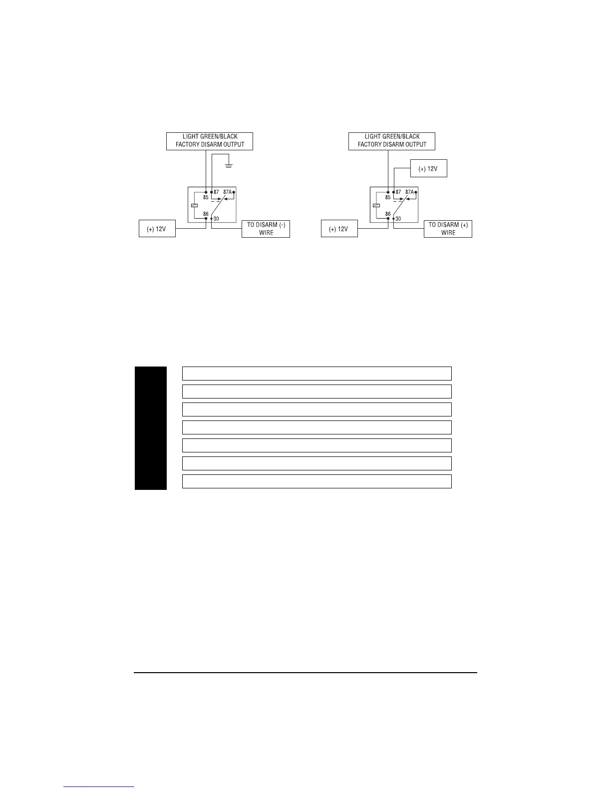
RReellaayy ffoorr NNeeggaattiivvee ((--)) DDiissaarrmm WWiirree RReellaayy ffoorr PPoossiittiivvee ((++)) DDiissaarrmm WWiirree
Door Lock Harness Wire Connection Guide
Relay Harness Wiring Diagram
___
___
___
___
___
___
___
*
NNOOTTEE
: VIOLET and VIOLET/BLACK are common at fuse holder.
The system has door lock relays on-board, and can directly interface with most electric power door
lock systems drawing 30 amps or less. It can also drive aftermarket actuators directly. (Some vehicles
require that an aftermarket actuator be added to the driver’s door to allow system control, see
Type
D
wiring section in
Tech Tip Document 1041
). The lock wire also supplies the output for the
comfort closure feature (if used).
VIOLET* Unlock #87 Normally Open (Input)
BLUE/BLACK Unlock #30 Common (Output)
BROWN/BLACK Unlock #87a Normally Closed
VIOLET/BLACK* Lock #87 Normally Open (Input)
GREEN/BLACK Lock #30 Common (Output)
WHITE/BLACK Lock #87a Normally Closed
BLACK/WHITE DomeLight Supervision relay Input #87
H2/A
H2/B
H2/C
H2/D
H2/E
H2/F
H2/G
 Loading...