6
©
2005
Directed Electronics, Inc.
H1/2 RED (+)12V constant power input
Before connecting this wire, remove the supplied fuse. Connect to the battery positive terminal or
the constant 12V supply to the ignition switch.
NNOOTTEE
: Always use a fuse within 12 inches of the point you obtain (+)12V. Do not use the 15 A fuse in
the harness for this purpose. This fuse protects the module itself.
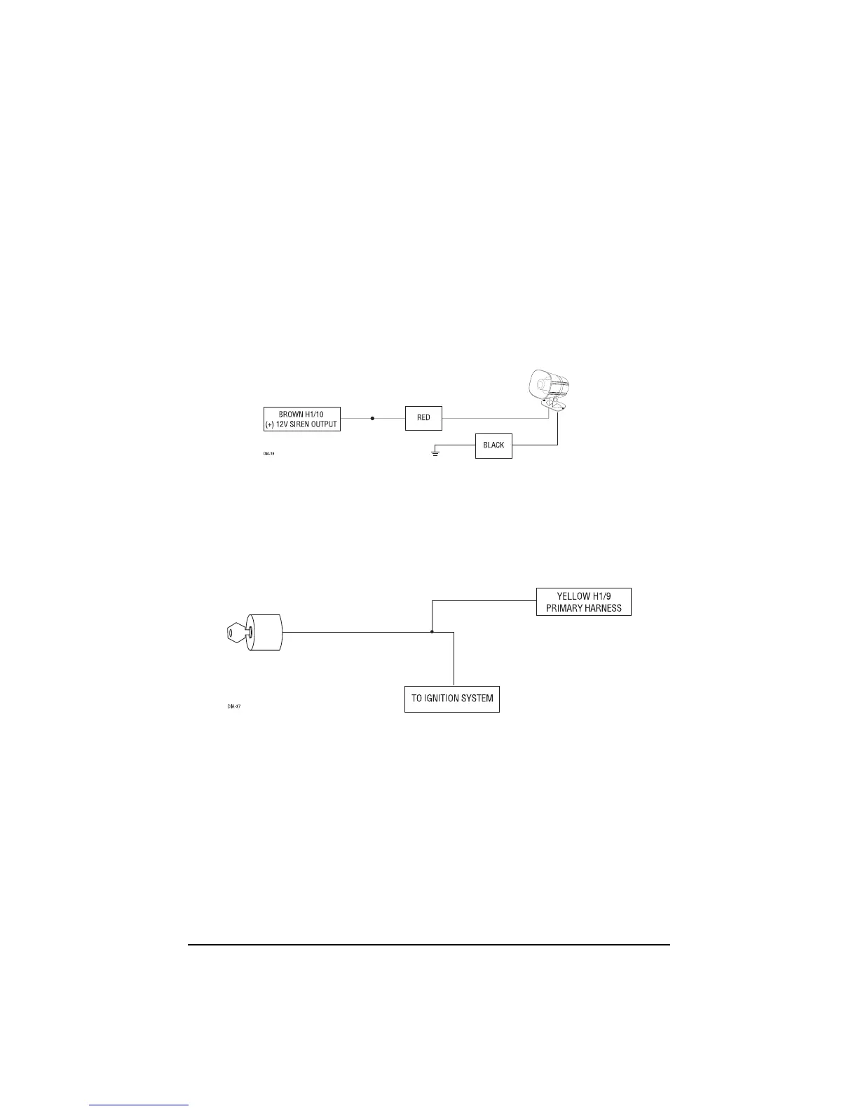
H1/3 BROWN (+) siren output
Connect this to the RED wire of the Revenger
®
siren. Connect the BLACK wire of the siren to (-)
chassis ground, preferably at the same point you connect the control module’s BLACK ground wire.
H1/4 YELLOW (+) ignition input
Connect this wire to the (+) 12 volts ignition wire. This wire must show (+) 12 volts with the key
in RUN position and during cranking. Take great care to ensure that this wire is not shorted to the
vehicle’s chassis at any point.
H1/5 BLACK (-) chassis ground connection
Connect this wire to a clean, paint-free sheet metal location (driver kick panel) using a factory bolt
that DOES NOT have any vehicle component grounds attached to it. A screw should only be used
when in conjunction with a two-sided lock washer. Under dash brackets and door sheet metal are
not acceptable ground points. It is recommended that all security components be grounded at the
same location.
 Loading...