Virginia Controls, LLC MH-3000 User Manual, 1_03C10-VC Page 44
5.5.2.5 I/O Bus Communication Connectors
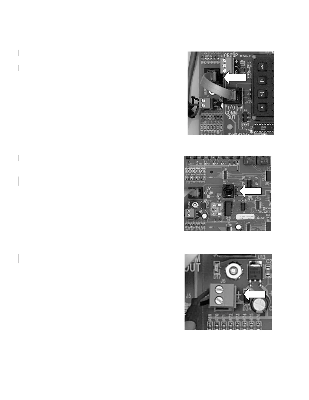
The connector on the left of the I/O board is for the
I/O bus from the CPU board.
It is connected in a daisy chain from the CPU to the
I/O boards. The I/O COMM OUT on the CPU is cabled to
the I/O COMM IN of the first I/O board. The I/O COMM
OUT of that board connects to the I/O COMM IN of the
next board, and so on.
The addresses of the boards must correspond to their
position in the daisy chain.
5.5.2.6 Programming Connector
This connector is used to program the
microprocessor on the I/O board. It is not used once
the I/O board is programmed.
5.5.2.7 Power Connector
This connector supplies 12VDC to the I/O board.
 Loading...