EasyManuals Logo

Vislink InCam-HG User Manual

Default Icon
43 pages
To Next Page IconTo Next Page
To Previous Page IconTo Previous Page
Page #20 background imageLoading...
Page #20 background image
Template Operators Manual
InCam Transmitter Connector Descriptions
Issue No: 1 Page: 20
Ref: INHG-ASUM-70XX Copyright © 2020 IMT and Vislink are Vislink Technologies Inc. companies
4.3.2. LMS-T Operation
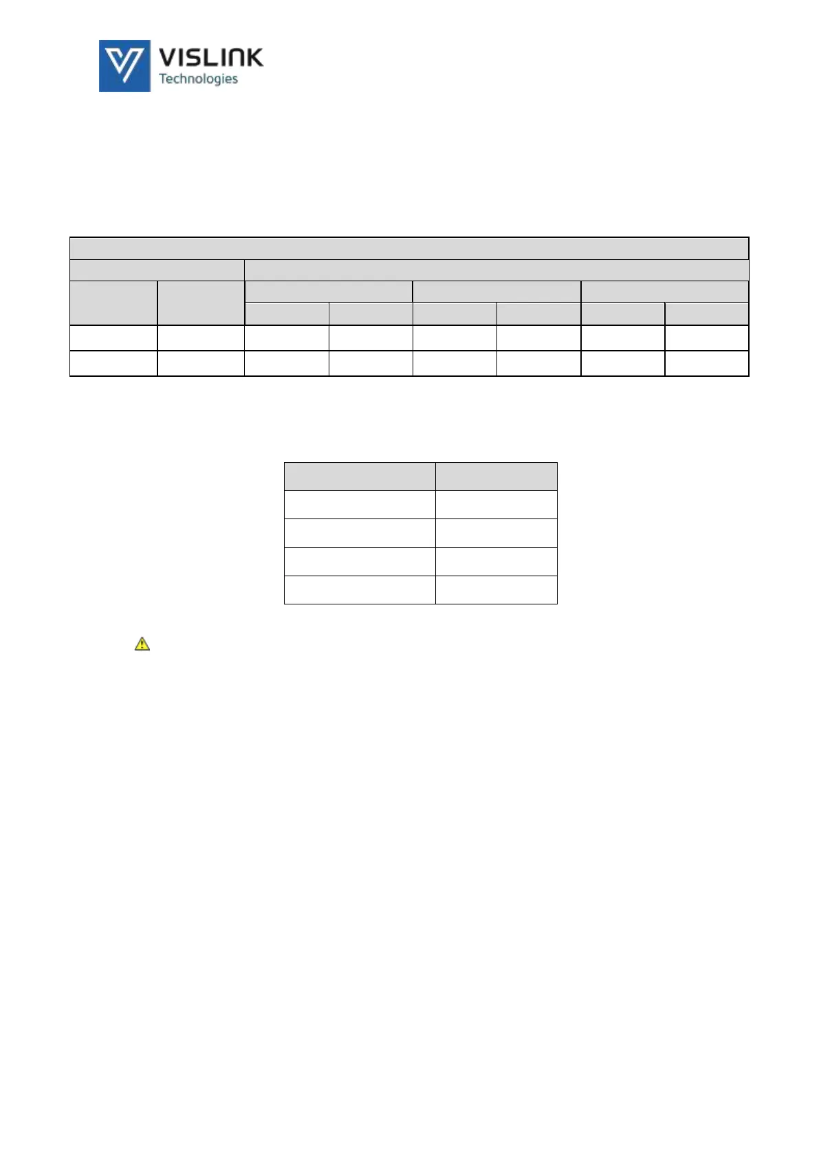
The table below defines the corresponding gross bit rates for LMS-T
operation at the most common bandwidths (Single or Dual pedestal):
Bitrates (Mbit/s) for a LMS-T system
Channels
Guard Interval
Modulation
Code Rate
10MHz
20MHz
24 MHz
1/8
1/16
1/8
1/16
1/8
1/16
QPSK
2/3
9.2
9.7
18.4
19.5
22.1
23.4
16QAM
2/3
18.4
19.5
36.8
39
44.2
46.8
Table 4-3 LMS-T Bitrate Table
4.4. InCam Connections
4.4.1. External DC Input
EXT. DC IN 11-17V
Connection
1
GnD
2
N/C
3
N/C
4
+12 Volts
Table 4-4 DC Input Connection
WARNING: Battery input has priority over External DC Input
4.4.2. MON OUT
75Ω BNC chassis mounted socket,
SDI monitor output from View-Back receiver.
Output options:
Camera loop through 2SI Output 1 in 4K
View-Back decoder
4.4.3. VF VIDEO
75Ω BNC chassis mounted socket,
SDI Viewfinder output.
NOTE: Viewfinder output menu not available in 4K formats

Table of Contents

Questions and Answers:

Question and Answer IconNeed help?

Do you have a question about the Vislink InCam-HG and is the answer not in the manual?

Vislink InCam-HG Specifications

General IconGeneral
BrandVislink
ModelInCam-HG
CategoryTransmitter
LanguageEnglish

Related product manuals