Home
Vislink
Receiver
RCD9
Page 37 (Table A-1 DVB-T Bit Rates for 6, 7 & 8 Mhz)
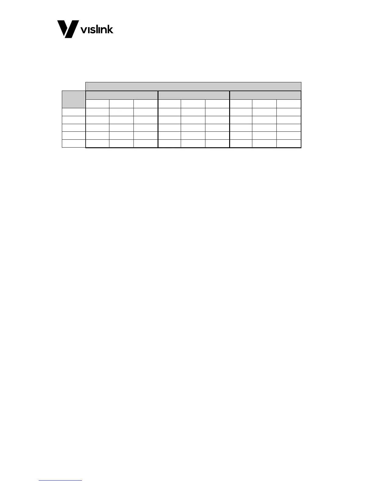
Vislink RCD9 - Table A-1 DVB-T Bit Rates for 6, 7 & 8 Mhz
38 pages
Manual
Save Page as PDF
To Next Page
To Next Page
To Previous Page
To Previous Page
Loading...
RCD9 Receiver Operator
s Manual
DVB
-T Non-Hierarchical Bit
-Rates
Issue No: 1
Page:
31
Ref: RCD9-A
SUM-
7001
Copyright © 2017 IM
T Ltd, trading as Visl
ink
A
p
p
e
n
d
i
x
A
D
V
B
-
T
N
o
n
-
H
i
e
r
a
r
c
h
i
c
a
l
B
i
t
-
R
a
t
e
s
A
.
1.
D
V
B
-
T
B
i
t
R
a
t
e
s
f
o
r
6
,
7
&
8
M
Hz
Guard Inter
val
Code
Rate
1/32
1/8
1/4
QPSK
16QAM
64QAM
QPSK
16QAM
64QAM
QPSK
16QAM
64QAM
1/2
4.52
9.08
13.57
4.14
8.29
12.44
3.73
7.46
11.19
2/3
6.03
12.06
18.08
5.52
11.05
16.58
4.97
9.95
14.92
3/4
6.78
13.57
20.35
6.22
12.44
18.66
5.59
11.19
16.79
5/6
7.54
15.08
22.62
6.91
13.82
20.73
6.22
12.44
18.66
7/8
7.91
15.83
23.75
7.25
14.51
21.77
6.53
13.06
19.59
Table A-1
DVB
-T Bit Rates for 6, 7 & 8
MHz
36
38
Table of Contents
Main Page
Default Chapter
1
User Manual
1
Table of Contents
4
1 General Information
7
General Safety Information
7
Disposal Instructions
8
Environmental
8
Health & Safety
9
Maximum RF Power Density Limits
10
2 Introduction
11
3 Specifications
13
Dual Diversity Receiver Head Unit
13
Table 3-1 Dual Diversity Receiver Specification
13
2/4-Way Diversity Receiver Control Unit
14
Table 3-2 2/4-Way Diversity Receiver Specification
15
4 MVL-HD3 Diversity Control Unit
17
Front Panel Layout
17
Rear Panel Layout
17
Connectors and Pinouts
17
Mains Power
17
Figure 4-1 Front Panel Layout
17
Figure 4-2 Rear Panel Layout
17
Table 4-1 Mains Power Pinouts
17
DC Power
18
Analogue Video Output
18
Sdi/Asi Outputs (2)
18
Table 4-2 Mains Power Pinouts
18
Analogue Audio
19
Digital Aes3/Ebu Audio and Dolby Pass-Through
19
Table 4-3 Analogue Audio Pinouts
19
Table 4-4 Digital Audio & Dolby Pass-Through
19
USB Port
20
Ethernet Remote (Rear Panel Connector)
20
Hdmi
20
Tsoip
20
Option (Front Panel Connector)
20
Data (Front Panel Connector)
20
Triax
20
Table 4-5 Data Pinouts
20
5 Dual Diversity Receiver Head Unit
21
Connectors and Pin Outs
21
RF Inputs
21
Triax Connector
21
DC Input
21
Remote
21
Table 5-1 DC Input Pinouts
21
Table 5-2 Remote Pinouts
21
6 Control Menus and Receiver Operation
23
On/Off Switches
23
Status LED
23
Local LED
23
Operator Controls
23
Video Monitoring on the Front Panel LCD Screen
23
Receiver Current Status and Alarm Screens
23
Table 6-1 Status LED Overview
23
Table 6-2 Local LED Overview
23
Overview Screen
24
Additional Status and Alarm Screens
24
Signal Status
24
Figure 6-1 Overview Screen
24
Figure 6-2 Signal Status Overview
24
Service Information
25
Decoder Status
25
Unit Information & Alarms
25
Figure 6-3 Service Information Screen
25
Figure 6-4 Decoder Status Screen
25
Figure 6-5 Unit Information & Alarms Screens
25
Setup Menus
26
Channel Frequency Menu
26
Channel
26
Preset Config
26
Channel Config
26
Figure 6-6 Setup Menus
26
Figure 6-7 Channel Screen
26
Spectrum and Bandwidth
27
Inputs Menu
27
Demodulator
27
Decoder
27
Outputs Menu
27
Analogue Outputs
27
Digital Outputs
27
Ports Menu
28
User Data
28
Ethernet
28
ASI over IP Menu
28
General Settings Menu
28
Software Versions
28
Display
28
Unit Name
28
Temperatures
29
Advanced Mode
29
USB Upgrade
29
Receiver Menu Tree
29
7 Preparing for Operation
35
Equipment Operation
35
MVL HD3 Diversity Receiver
35
Antennas
35
Checks
35
Transmitter/Receiver Tests
35
Table A-1 DVB-T Bit Rates for 6, 7 & 8Mhz
37
Table B-1 Glossary of Terms
38
Appendix B Glossary of Terms
38
Related product manuals
Vislink Lynx L2174
26 pages
Vislink UltraReceiver LD
38 pages
Vislink UltraReceiver
42 pages
Vislink Quantum
75 pages