Issue No: 1 Page: iv
Ref: RCD9-ASUM-7001 Copyright © 2017 IMT Ltd, trading as Vislink
Table of Contents
1. General Information .................................................................................................. 1
General Safety Information ........................................................................................................ 1
Disposal Instructions .................................................................................................................. 2
Environmental ............................................................................................................................ 2
Health & Safety .......................................................................................................................... 3
Maximum RF Power Density Limits ........................................................................................... 4
2. Introduction .............................................................................................................. 5
3. Specifications ............................................................................................................ 7
Dual Diversity Receiver Head Unit ............................................................................................. 7
2/4-way Diversity Receiver Control Unit .................................................................................... 8
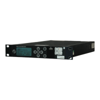
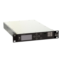
4. MVL-HD3 Diversity Control Unit ............................................................................... 11
Front Panel Layout ................................................................................................................... 11
Rear Panel Layout .................................................................................................................... 11
Connectors and Pinouts ........................................................................................................... 11
4.3.1. Mains Power ............................................................................................................................ 11
4.3.2. DC Power.................................................................................................................................. 12
4.3.3. ANALOGUE VIDEO OUTPUT ..................................................................................................... 12
4.3.4. SDI/ASI OUTPUTS (2) ................................................................................................................ 12
4.3.5. ANALOGUE AUDIO ................................................................................................................... 13
4.3.6. DIGITAL AES3/EBU AUDIO AND DOLBY PASS-THROUGH ........................................................ 13
4.3.7. USB Port ................................................................................................................................... 14
4.3.8. Ethernet Remote (rear panel connector) ................................................................................ 14
4.3.9. HDMI ........................................................................................................................................ 14
4.3.10. TSoIP ...................................................................................................................................... 14
4.3.11. Option (front panel connector) ............................................................................................. 14
4.3.12. Data (front panel connector) ................................................................................................. 14
4.3.13. Triax ....................................................................................................................................... 14
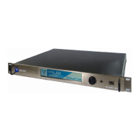
5. Dual Diversity Receiver Head Unit ............................................................................ 15
Connectors and Pin Outs .......................................................................................................... 15
5.1.1. RF Inputs .................................................................................................................................. 15
5.1.2. Triax Connector ........................................................................................................................ 15
5.1.3. DC Input ................................................................................................................................... 15
5.1.1. Remote ..................................................................................................................................... 15
6. Control Menus and Receiver Operation ................................................................... 17
On/Off Switches ....................................................................................................................... 17
Status LED ................................................................................................................................. 17
Local LED .................................................................................................................................. 17
Operator Controls .................................................................................................................... 17
Video Monitoring on the Front Panel LCD Screen ................................................................... 17
Receiver Current Status and Alarm Screens ............................................................................ 17
6.6.1. Overview Screen ...................................................................................................................... 18