VIVOTEK - A Leading Provider of Multimedia Communication Solutions
4 - User's Manual
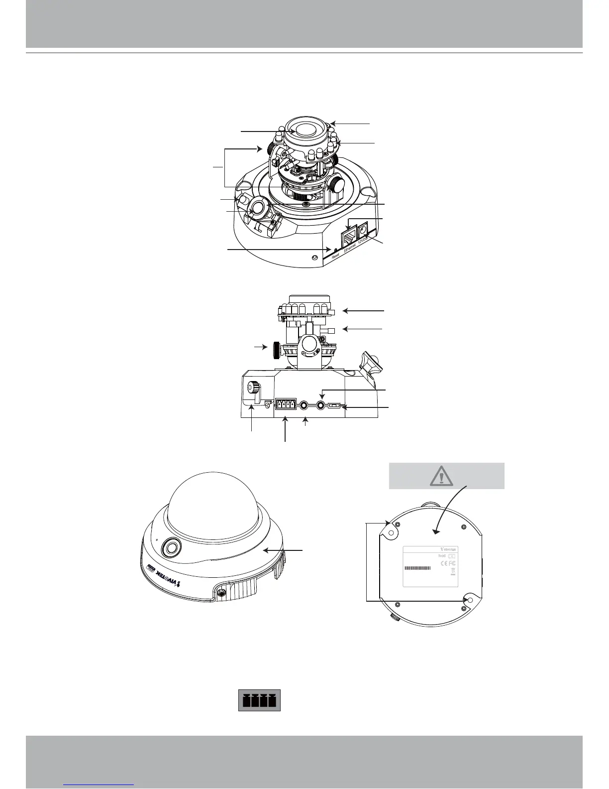
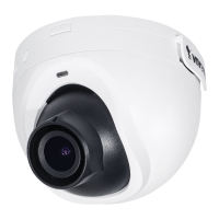
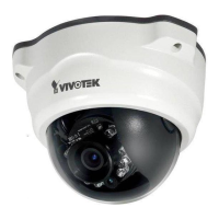
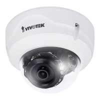
Physical description
General I/O Terminal Block
This Network Camera provides a general I/O terminal block which is used to connect external
input / output devices. The pin definitions are described below.
1 2 3 4
1: Power
2: Digital output
3: Digital input
4: Ground
Lens
Tilt screw
Built-in MIC
PIR sensor
IR LEDs
Power cord socket
Ethernet 10/100 RJ45 socket
Indented reset button
Audio Out Mic. In Ext. Int.
1 2 3 4
I/O
Focus controller
Zoom controller
General I/O terminal block
Audio out
MIC in
External/Internal MIC switch
Keep a note of the MAC address
before installing the camera.
Network Camera
Model No: FD7132
Made in Taiwan
This device complies with part 15 of the FCC rules. Operation is subject to
the following two conditions:
(1)This device may not cause harmful interference, and
(2) this device must accept any interference received, including interference
that may cause undesired operation.
Pat. 6,930,709
RoHS
C I
MAC:0002D107258A
Drill holes
Pan screw
Dome cover
Image adjustment screw
Status LED
Light sensor