VIVOTEK - A Leading Provider of Multimedia Communication Solutions
User's Manual - 5
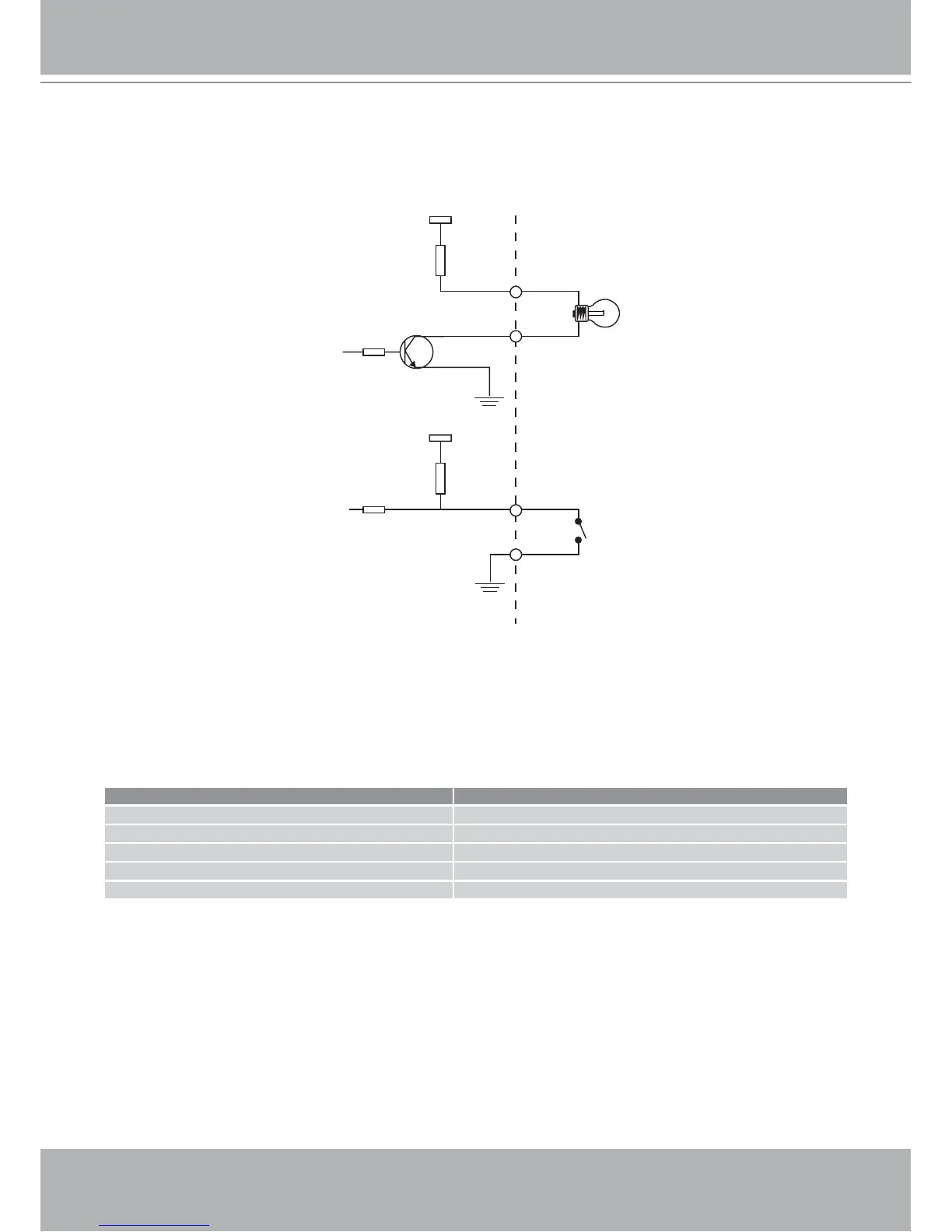
DI/DO Diagram
Refer to the following illustration for connection method.
12V
+12V
Digital output
PIN 1
Power+12V
PIN 2
Digital input
PIN 3
Ground
PIN 4
Status LED
The LED indicates the status of the Network Camera.
Description Status LED
Blinking green and orange (twice) Power on or reset
Non light During booting procedure
Steady orange till IP address is confirmed Detecting and setting network
Blinking orange and red continuously After network is setup (system up)
Rapidly blink orange till firmware is upgraded During the upgrade firmware process