VIVOTEK - Built with Reliability
User's Manual - 27
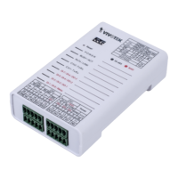
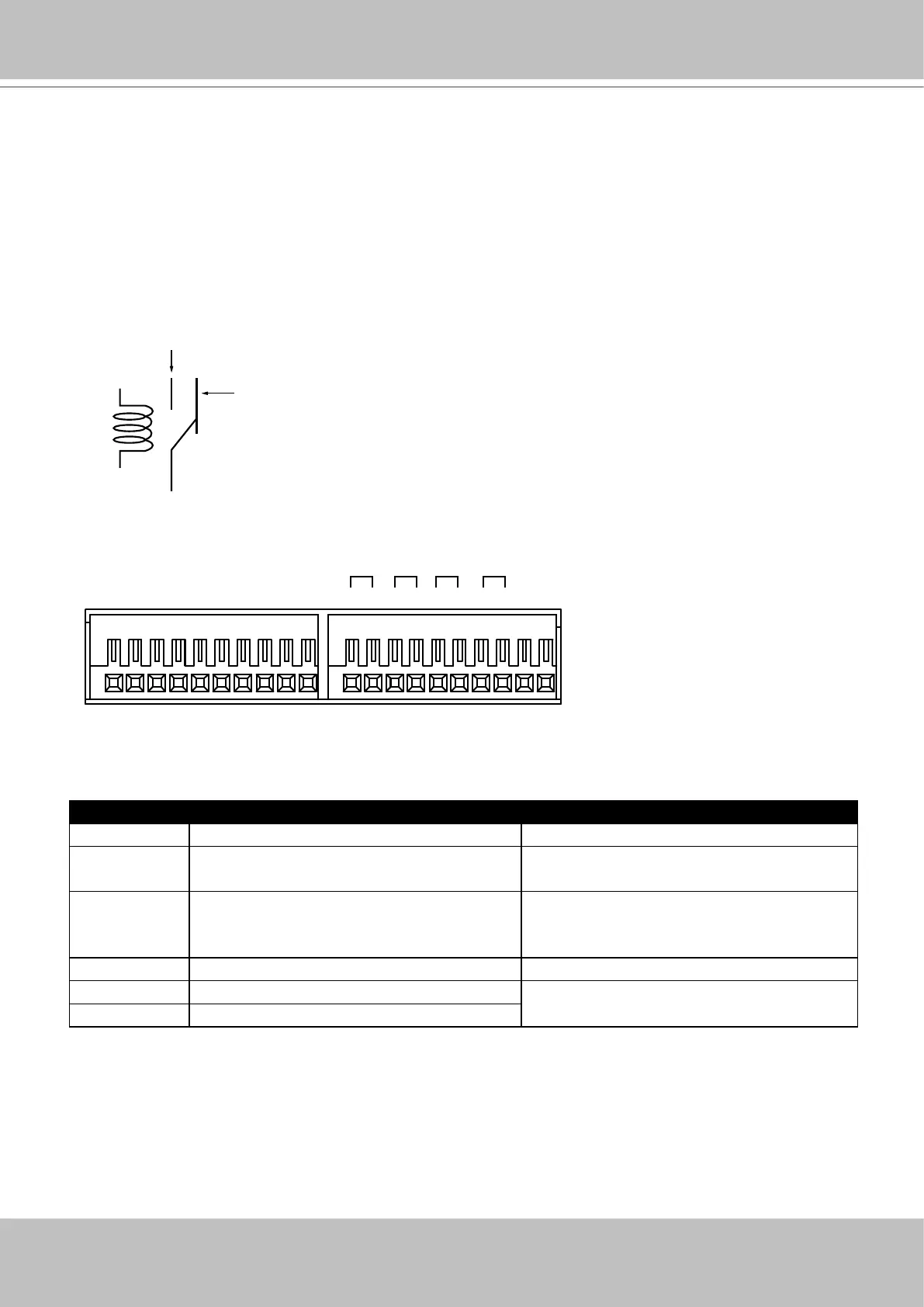
Terminal Block Connections
The terminal block pinouts is shown as follows:
The DO pins default status is set to Normally Closed. Connect your relay or external devices’
signal wires to the system, the system will automatically detect the current signal status. You
can then trigger the external devices using the DI/DO panel on the live view.
You can also congure the system alarm setting for the system to automatically trigger a DO on
the occurrence of system events. See Alarm settings on page 111.
The pins are listed and described from left to right as shown in the drawing above.
Pin Description NOTE
DI no. 1 ~ 8 Open-short-to-GND
G Pins #1~4 share a common ground.
Pins #5~8 share a common ground.
NO Normally open. Use the DO trigger
buttons on the live view window to
trigger the digital output.
COM Common pin
RS485+ RS485 Data+ A 120Ω terminator is enabled on the
bus. The terminator cannot be disabled.
RS485- RS485 Data-
RS485
+
-
4321
Alarm OUT
G8765 G4321
Alarm IN
NO COM NO COMNO COM NO COM
NO = Normally Open
COM = Common pin
Normally Open
pin
Common pin
Normally Closed
pin
Coil
 Loading...