10-2
10TA Service Manual
OPTIONS AND ACCESSORIES
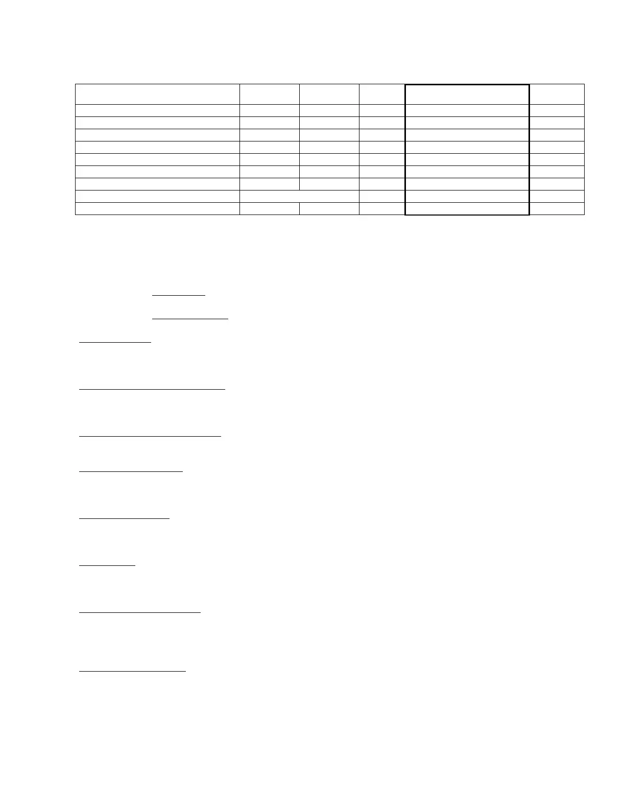
Parameter limits
Parameter Minimum Maximum Default Recommended Settings Unit
Line Side Voltage (Nominal Voltage) 90 650
Volts
Over Voltage
(tolerance) 6 18
%
Under Voltage
(tolerance) 6 18
%
Phase Unbalance 2 25
%
Lockout Time (Delay on Break) 0.1 25
Seconds
Delay Time (Delay on Make) 0 30
Seconds
Response Time (Delay on Fault) 0.1 20
Seconds
Control Mode Off / Auto / On
N/A
Contactor Test OFF 5
Volt Diff
TABLE 10-1
Power Monitor Parameters
Parameters adjustment (in order of display)
Active display of Line Voltage (this is the default normal display)
Active display of Load Side Voltage (if connected)
Voltage Set Point
(VAC Flashes) The value may be adjusted by pressing the up and down arrows. This may be set to the normal
operating voltage of the device being protected in one volt increments.
Under/over Voltage Tolerance in %
(UNDERVOLTAGE/OVERVOLTAGE flashes)
The value may be adjusted by pressing the up and down arrows.
Imbalance Voltage Tolerance in %
(% IMBALANCE flashes) The value may be adjusted by pressing the up and down arrows.
Lockout Time in seconds
(SECONDS flashes) The value may be adjusted by pressing the up and down arrows. (This is the delay on break timer
value)
Delay time in seconds and tenths of seconds
(RESP. SECONDS flashes) The value may be adjusted by pressing the up and down arrows. This is the time that a
fault is allowed before shutdown occurs.
Control mode
(ON OFF AUTO flashes) The value may be adjusted to OFF (load will not turn on), ON (load will turn on whenever
there are not faults and timers are finished) and AUTO (Load will turn on when there is a control input).
Contactor fault monitor mode
(CONTACTOR FAULT flashes) This option allows you to monitor the contactor and lock it out if the line voltage and
load side varies by more than 5 volts. Pressing the up and down arrows selects off (default) or on. The load side of the
contactor must be connected to the load terminals of the DTP-3 to use this option.
Display of fault memories
(MEM flashes) Pressing up or down displays the last fault conditions that took the unit off line. The first 25 faults are
recorded. The top number displayed represents the fault memory. The middle number represents the total number of
faults that have occurred since the fault memory was cleared.
To clear the memory, press and hold the up and down keys until the display is cleared.