10TA Service Manual
SERVICE OPERATIONS
4/28/14
9-3
Hand Expansion Valve (Part No. 12A4200C0605) The hand expansion valve is located after the
liquid feed solenoid valve (“A1” Valve). This valve should be set at a point where the float switch is
open for a length of time approximately equal to the time it is closed. The factory setting is about 2
turns from full open.
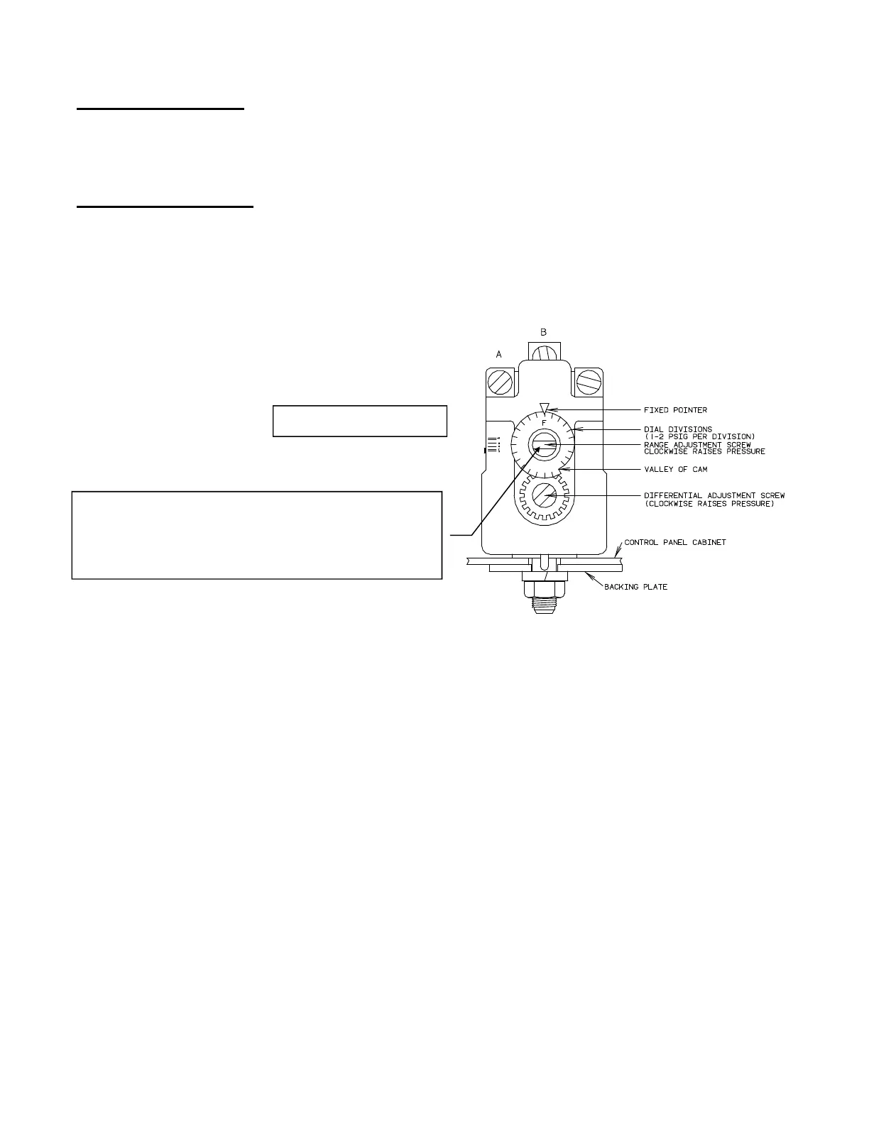
Freezer Pressure Switch (Part No. 12A2117E04) The freezer pressure switch (FPS), located inside
the control panel, controls the freezing time period for the production of cylinder or crushed ice.
This switch was set at the factory to produce ice of recommended thickness. Look at the “Certificate
of Test” which was provided with the machine for a sample set of pressure readings with
corresponding time periods and water temperatures. Also see TABLE 11-6, Operating Vitals for
typical settings. Do not make adjustments until several ice discharging cycles have been completed.
FIGURE 9-3
Freezer Pressure Switch
The following procedure is recommended for initially setting a freezer pressure switch that has not
been previously adjusted (See FIGURE 9-2):
1. Turn the bottom screw (differential) approximately 1/2 turn to the Left (counter clockwise).
The pointer arrow, which is at the top middle of the switch, will be at the “F” setting.
2. Turn the top screw (range adjustment) approximately 4 1/2 turns to the Left (counter
clockwise). The pointer on the range setting will be between 40 psi and 50 psi.
3. After the machine is running, the range adjustment (top screw) will have to be fine-tuned to get
the proper ice thickness. (Clockwise = Thinner Ice) (Counter Clockwise = Thicker Ice)
The freezing time can be such that a small percentage of the ice is frozen solid. If so, some ice from
the top and bottom of the freezer should have a small hole in the center to insure that the freezing
time has not been extended to where a loss in capacity would result.
It is preferable that the freezing cycle be such that a small diameter hole remains in the center of the
ice cylinder. (1/16” diameter for 7/8” diameter ice, 1/8” diameter for 1 1/8” diameter ice) This
insures that the freezing cycle is not extended unnecessarily and eliminates a possible opaque core in
the center of the ice.
Turn top screw to adjust the pressure setting
(also referred to as the Range)
Clockwise = increase pressure setting (thinner ice)
Counterclockwise = decrease pressure setting (thicker ice)
Part No. 12A2117E04