10TA Service Manual
TABLE OF CONTENTS
i
TABLE OF CONTENTS
Vogt
®
TUBE-ICE
®
MACHINES
Model 10TA (Includes P18FXT)
Page No.
1. INTRODUCTION
A Brief History Of Our Company ................................................................................................................................. 1-1
Vogt Energy-Savings Tube-Ice® Machines .................................................................................................................. 1-1
Preview ..................................................................................................................................................................... 1-1
Important Safety Notice ................................................................................................................................................. 1-2
Special Precautions To Be Observed When Charging Refrigeration Systems ............................................................... 1-2
Safety Symbols and What They Mean ........................................................................................................................... 1-3
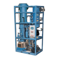
Assembly Drawing Model 10TA (P18FXT) Air-Cooled, FIGURES 1-1, 1-2, & 1-3 ................................................... 1-4, 1-5, 1-6
Assembly Drawing Model 10TA (P18FXT) Water Cooled, FIGURES 1-4, 1-5, & 1-6 ............................................... 1-7, 1-8, 1-9
2. RECEIPT OF YOUR TUBE-ICE MACHINE
Inspection ..................................................................................................................................................................... 2-1
Safety Valves ................................................................................................................................................................. 2-1
Machine Room .............................................................................................................................................................. 2-1
Storage (prior to installation and start-up) ..................................................................................................................... 2-2
Vogt Model Nomenclature, FIGURE 2-1 ...................................................................................................................... 2-2
3. INSTALLING YOUR TUBE-ICE MACHINE
Piping and Drain Connections, TABLE 3-1 ................................................................................................................. 3-1
Water Cooled Condenser Connections, FIGURE 3-1 .................................................................................................... 3-2
Cooling Tower ............................................................................................................................................................... 3-2
Space Diagram (Air-Cooled Machine), FIGURE 3-2A ................................................................................................. 3-3
Space Diagram (Water Cooled Machine), FIGURE 3-2B ............................................................................................. 3-4
Wiring and Electrical Connection FIGURE 3-3 ............................................................................................................ 3-5
Electrical Specifications, TABLE 3-2 ........................................................................................................................... 3-5
Phase Check, Voltage and Current unbalance ............................................................................................................... 3-6
Rotation Check .............................................................................................................................................................. 3-6
Air-Cooled Condenser Installation Instructions ............................................................................................................. 3-7,3-8
Pounds of R-22 to Add Vs. Liquid Line Length, TABLE 3-3 ....................................................................................... 3-8
Air-Cooled Condenser Data, TABLE 3-4 ...................................................................................................................... 3-9
Condenser Dimensions, FIGURE 3-4 ............................................................................................................................ 3-10
Condenser Field Piping (Cold Weather Valve Kit), FIGURE 3-5 ................................................................................. 3-11
Equivalent Feet Due To Friction, TABLE 3-5 ............................................................................................................... 3-12
Minimum Traps For Discharge Lines, FIGURE 3-6 ..................................................................................................... 3-12
Wiring For Bohn BNHS04A029 Condenser (3 phase motors), FIGURE 3-7 ................................................................ 3-13
Ice Bin Thermostat Sensor ............................................................................................................................................. 3-15
Typical Bin Sensor Mounting, FIGURE 3-9 ................................................................................................................. 3-15
Programming Electronic Bin Thermostat ...................................................................................................................... 3-16
Installation Review: A Checklist .................................................................................................................................. 3-17