10TA Service Manual
SERVICE OPERATIONS
4/28/14
9-12
0
2
4
6
8
10
12
RANGE UNIT
POWER
UP
Min
FIGURE 9-9A
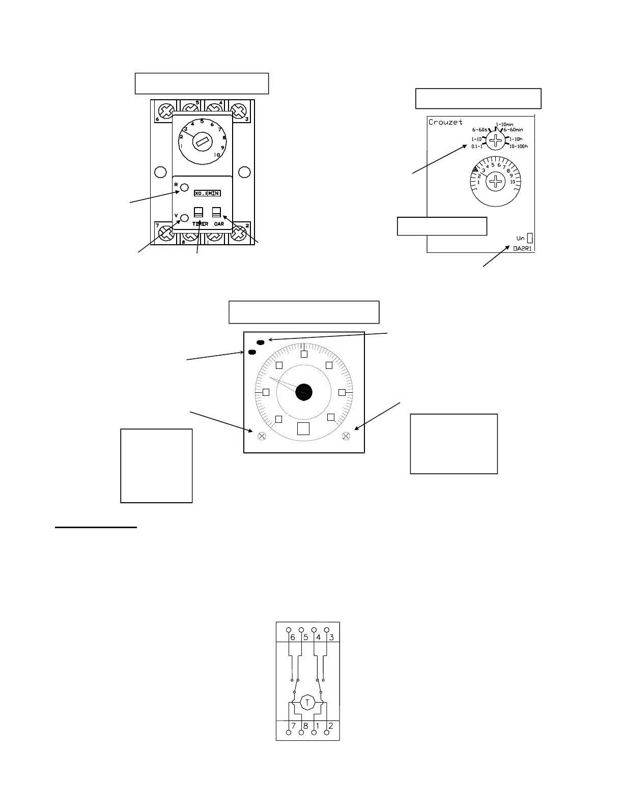
Thawing Timer
Thawing Timer (Part No. 12A7503E22) The thawing timer governs the ice thawing period. It is
located inside the control panel (FIGURE 6-2). It is started by action of the freezer pressure switch
(FPS) which energizes the “CR” relay.
Set the thawing period for at least 30 seconds longer than the time required to harvest the entire
discharge of ice. If it should be necessary to change the setting of the timer, turn the adjustment
screw clockwise to increase the time or counter-clockwise to decrease the time. Verify time after
each adjustment.
FIGURE 9-9B
Thawing Timer Wiring
Syrelec Timer (Orange)
Light
indicates
timer is timing
Light
indicates
timer has
timed out
Time Base:
Set to “min”
Scale: Set to
“X1”
Crouzet Timer (White)
Light flashing when timing
Light Solid when timed out
Range: Set
to “1-10
min”
Voltage rating: 24-240V
Allen Bradley Timer (White)
Range: Set to
“0 to 12”
Time Range
adjustment
0 - 1.2
0 - 3
0 - 12
0 - 30
Unit adjustment
sec
min
hrs
10h
Power Light (green)
Light blinks while "timing"
Up Light (red)
Light off while "timing"
Units: Set to “min”