EasyManuals Logo

Vogtlin V-Flow Series User Manual

Vogtlin V-Flow Series
38 pages
To Next Page IconTo Next Page
To Previous Page IconTo Previous Page
Page #21 background imageLoading...
Page #21 background image
V-Flow Line
Manual
Version
Page
V-Flow Line
vflow_E4_7
21
Limit indicator
The V-100 variable area flowmeters can be equipped with a maximum of two limit indicators.
The instruments with limit indicators have the following standard design:
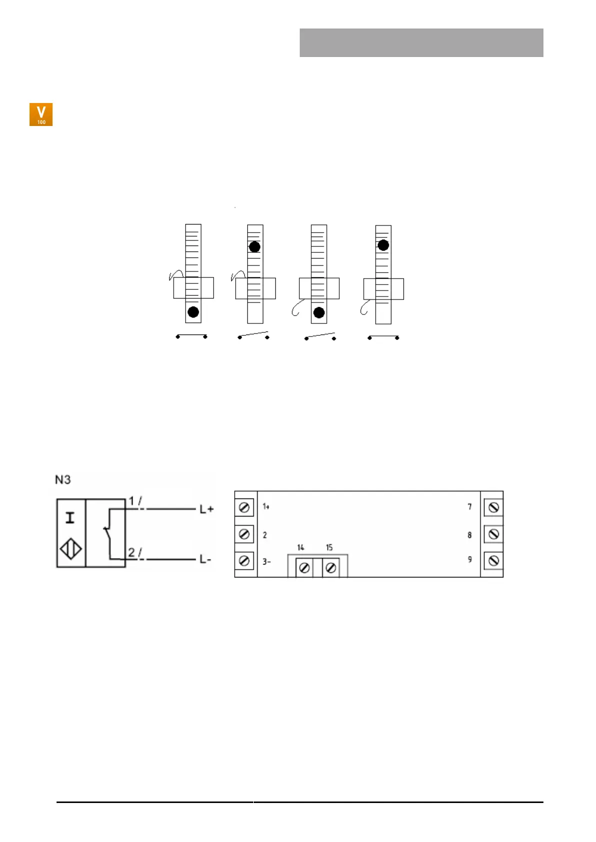
Minimum Switch Maximum Switch
Initiator position
Switching status
Note: In case of power failure, the contact closes irrespective of the position of the float.
For initialization, the float must first pass the initiator so that it is recognized by the initiator and the
float position is defined.
Wiring diagram
Limit indicator RC-10../RC-15, e.g. Pepperl + Fuchs Type KFD2-SR2-Ex1.W (24 VDC)
brown
blue

Questions and Answers:

Question and Answer IconNeed help?

Do you have a question about the Vogtlin V-Flow Series and is the answer not in the manual?

Vogtlin V-Flow Series Specifications

General IconGeneral
BrandVogtlin
ModelV-Flow Series
CategoryMeasuring Instruments
LanguageEnglish