Electrical Installations
An incorrectly designed electrical installation may
generate leakage current from the electrical system.
Leakage current can in turn render galvanic protection
inadequate in respect of propellers, propeller shafts,
rudder posts, the keel etc., and may cause damage
through electrochemical corrosion.
WARNING!
Work on the low voltage circuits in the boats should be
done by a person with electrical training or knowledge.
Installation or work on land current equipment must
only be done by a competent electrician, in accordance
with local regulations for mains electricity.
The following must always be heeded:
1 If shore power is connected it must always be
ground protected ashore, never in the boat.
Furthermore, the shore power installation should be
equipped with a ground fault circuit interrupter.
The shore power installation (transformer, inverter,
battery charger etc.) must be designed for marine
use where the high-tension side is galvanically
separated from the low-tension side.
2 Electrical cables must be run and clamped such
that there is no risk of exposure to chafing, damp or
bilge water.
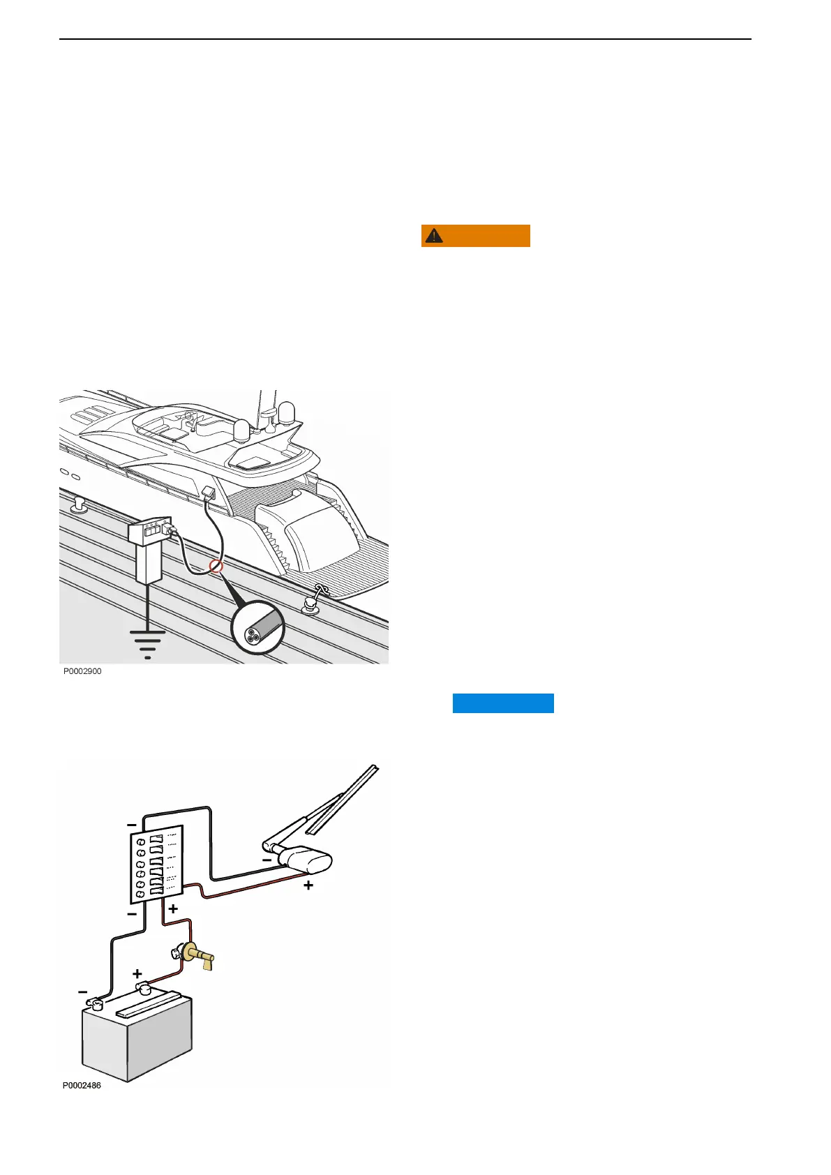
3 Ground protection for radios, navigation
instruments, rudder, boarding ladders or other
equipment where separate cables for ground
protection are present, must be clustered to a
common ground connection that is not connected
to the engine or reverser gear.
IMPORTANT:
The engine and reversing gear must never be
used as earth planes.
4 The start battery must have a main switch (1)
connected to the battery's positive (+) side. The
main switch must break the circuit to all equipment
and be switched off when the boat is not in use.
5 If an auxiliary battery is used, a main switch must be
placed between the auxiliary battery's positive (+)
terminal and the circuit breaker panel for the boat's
electrical equipment. The main switch must break
the circuit to all equipment connected to the
auxiliary battery and must be switched off when
power is no longer required. All equipment
connected to the auxiliary battery must have
separate main switches.
For simultaneous charging of two independent battery
circuits a separate charging distributor (accessory)
should be installed on the standard alternator.
Maintenance
128 47713726 12-2021 © AB VOLVO PENTA
 Loading...