Maintenance
Maintenance every 1000 operating hours 83
Checking, if necessar y adjusting the valve
clearance
– Check the valve clearance only when the engine is cold.
– Remove the cylinder head cover.
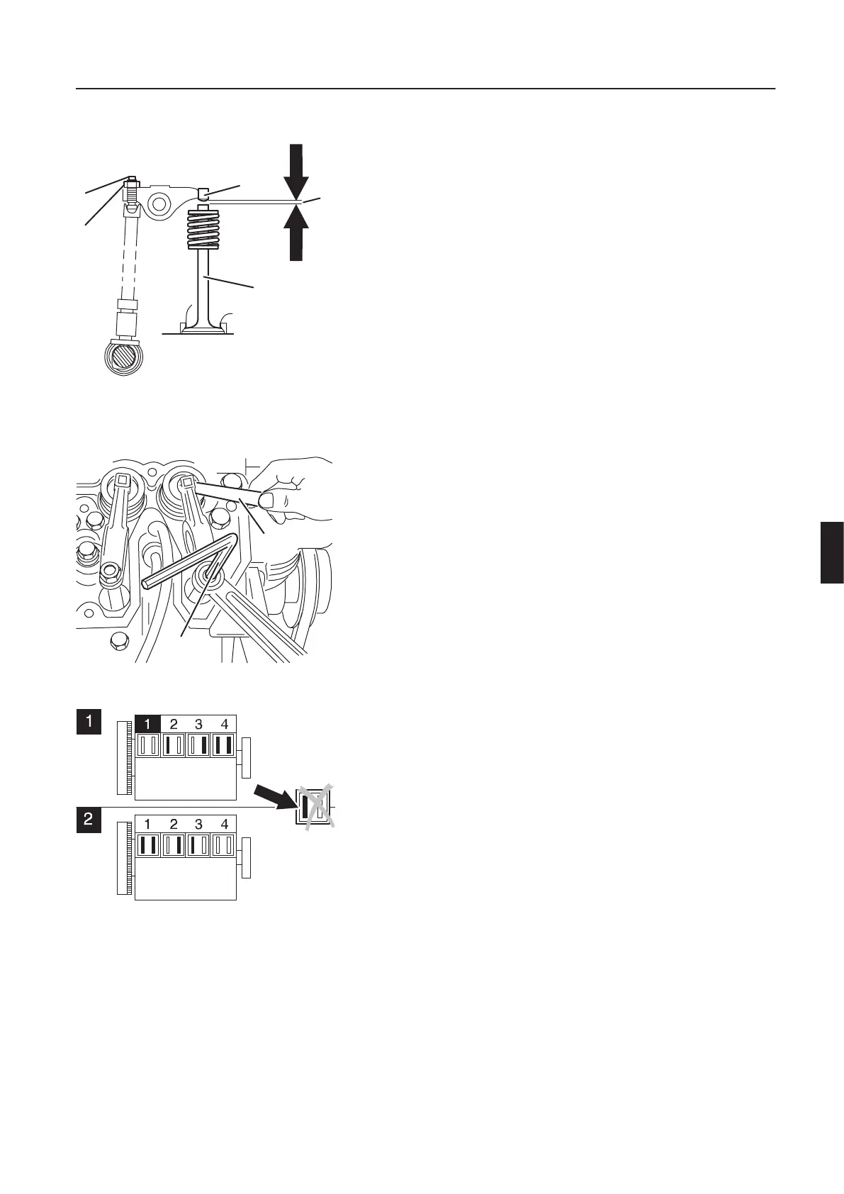
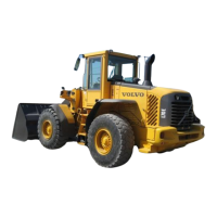
– Check the valve clearance (1) between rocker arm (2) and
valve (3) with a feeler gauge (6) (it must be possible to push the
feeler gauge in against a slight resistance).
– Permitted valv e clearance: Inlet valve 0.3 mm / 0.012 in
(on cold engine) Exhaust valve 0.5 mm / 0.020 in
– Sense of rotation of the engine counter-clockwise, when looking
onto the flywheel.
– Firing sequence: 1 - 3 - 4 - 2
Adjusting the valve clearance
– Loosen the counter nut (4).
– Regulate the adjustment screw (5) with an Allen key (7), so that
the correct valve clearance is reached after retightening the
counter nut (4).
– Perform tests and adjustments on each cylinder.
– Reassemble the cylinder hood with a new gasket.
Adjustment pattern for valve clearance adjustment
Crankshaft position 1:
Turn the crankshaft until both valves on cylinder (1) are overlap-
ping (exhaust valve not yet closed, inlet valve starts to open). Per-
form the adjustment of the valve clearance according to the
adjustment pattern, black marks. For control purposes you should
mark all adjusted valves with a chalk mark on the rocker arm.
Crankshaft position 2:
Turn the crankshaft one turn (360°) further. Perform the adjustment
of the valv e clearance according to the adjustment pattern, black
marks.
M300078A
2
1
3
5
4
M300079A
EX
IN
6
7
M300080A



 To Next Page