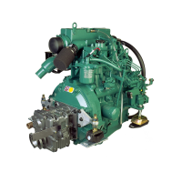
MD2040:
Place the expander (2, Fig. 52 on page
38) to the oil scraper rings in the piston ring groove.
Check that the ends on the expander do not over-
l
ap each other. Fit the top scraper ring (1) over the
the expander. Put in one end of the ring in the
groove and hold it in place with your thumb. Push
the ring in position with your other thumb.
Fit the lower scraper ring (3) in the same way.
Check that the scraper rings run easily in both di-
rections and that the ends on the expander and the
rings are in the correct position (Fig. 52).
Fitting of piston in cylinder
Note:
After replacing a connecting rod, piston or gudg-
eon pin the weight difference between the connecting
rod complete with piston and piston rings must not ex-
ceed 10 g (0.35 oz) between the different cylinders.
1.
Lubricate the piston and piston rings with engine oil
and turn the rings so that the oil penetrates the pis-
ton ring groove. Turn the piston rings so that the
piston ring gaps are divided by 900 from each other.
Note:
Make sure that no piston ring gap is posi-
tioned opposite the piston bolt or at right angles to
i
t.
MD2040:
Check that the ends on the expander and
scraper rings are in the correct position (Fig. 52).
2.
Place the bearing cups in their positions in the con-
necting rod and cap. Check that the hole in the
bearing cups comes opposite the hole in the con-
necting rod. Oil in the crank pin with engine oil.
Engine body
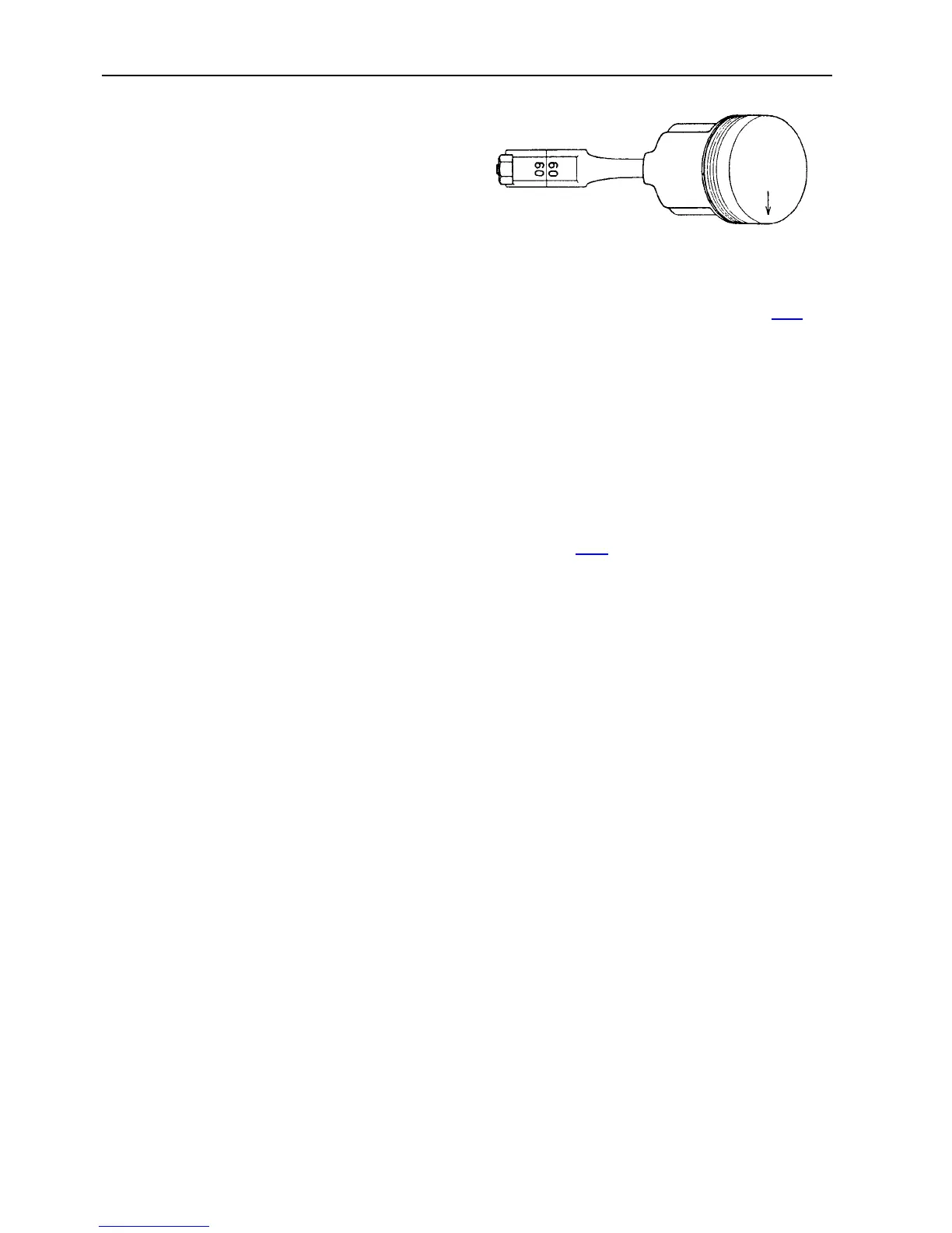
Fig. 53. Number marking on connecting rod and cap
3.
Check that the marking on the piston top,
alt. in
the
piston and on the connecting rod, correspond with
Fig. 53.
Use a piston ring compressor and fit the piston with
connecting rod in the respective cylinder, beginning
with cylinder No. 1 (first).
Note:
The connecting rod with the
l
owest number
should be fitted first (to cylinder No. 1) and subse-
quently the connecting rod with the highest number
closest to the flywheel.
The connecting rod should be turned with the mark-
i
ng (number/colour marking) turned "towards the in-
jection pump" (camshaft side). The arrow on the
piston top
alt. at
the gudgeon pin hole should there-
by point forwards.
4.
Fit the bearing cap and tighten the connecting rod
screws. See "Technical data" for tightening torque.
Note: The main bearing cap should be fitted so that
the number/colour marking on the crankshaft and
cap correspond (Fig. 53).
Undamaged connecting rod screws do not need to
be changed and can be re-fitted.
3
9
 Loading...