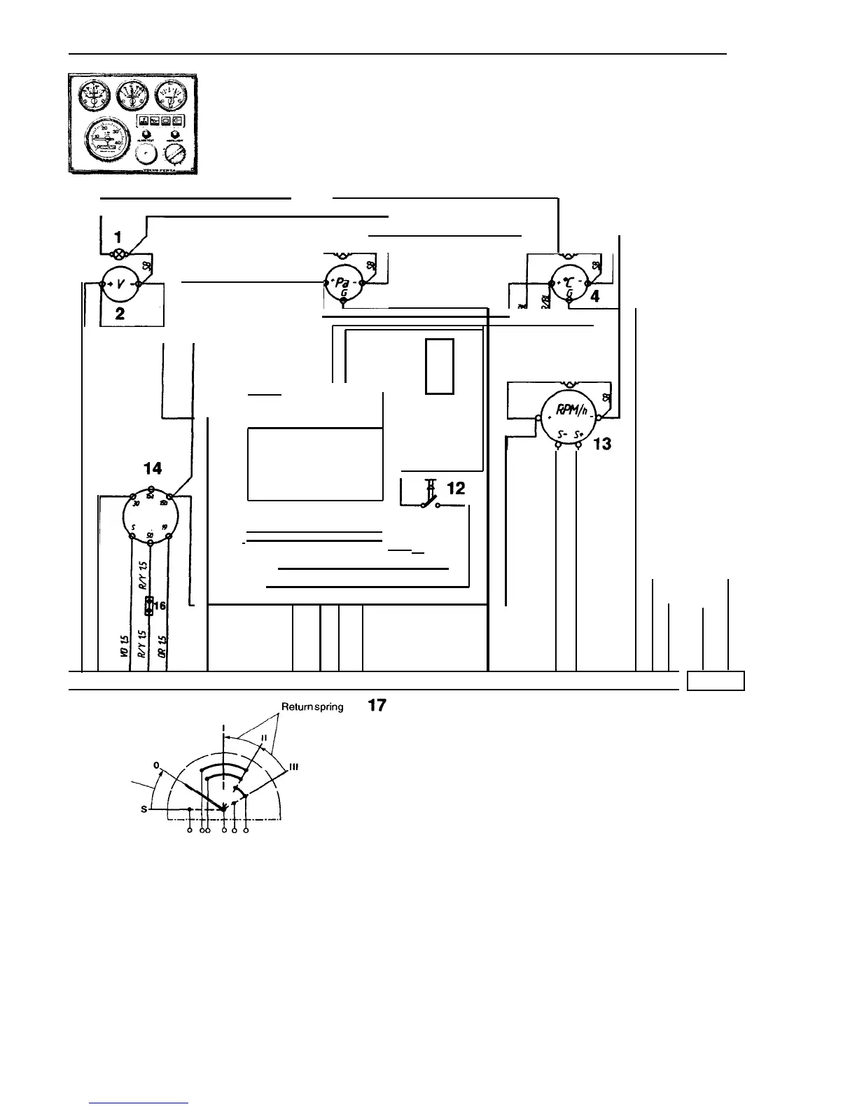
Wiring diagram
QC
8 6
cc
2
Return spring
4
Cable colour
BL
LBL
BN
LBN
GN
GR
OR
R
SB
VO
W
Y
af
SR
I
S 15815b 3050 19
Blue
•
Light blue
Brown
Light brown
•
Green
•
Grey
•
Orange
•
Red
•
Black
Violet
•
White
•
Yellow
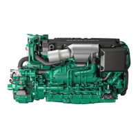
I
nstrument panel, alternative "C"
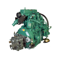
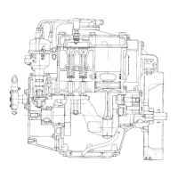
MD2010B/C, MD2020B/C, MD2030B/C, MD204OB/C
6
1
61
S
I
/
7
8
9
10
0 (9 (9 (9
W
a
BAT
&OW
S
k,
+ - +
S
11
.
A-
15
RIM
R
w/Sa
S8
5
ER
cc
S
u
S
12 13
11
8
avw is
atir
U
18
1.
I
nstrument lighting
2.
Voltmeter
3.
Oil pressure gauge
4.
Refrigerant temperature gauge
5.
Connector for connection of extra warning display
(accessory)
6.
Electronics unit (alarm)
7.
Warning lamp, refrigerant temperature
8.
Warning lamp, oil pressure
9.
Warning lamp, charging
10.
Control lamp, glowing
11.
Switch, instrument lighting
12.
Switch - alarm test/Acknowledging
13.
Tachometer with built-in hour counter (accessory),
alt. blind plug
14.
Key switch
15.
Alarm
16.
Connector for connection of neutral position switch
(accessory)
17.
16-pole connection
18.
2-pole connection (for extra panel)
Cable areas in mm
2
are given after the colour code in the wiring diagram.
Areas not given=
1.0 mm
2
 Loading...