E 2200, E 3000ES Accessories
wc_tx001668gb.fm 75
3. Remove hose loop 2 from the HHS and store the HHS in a secure location.
4. Connect HHS hose loop 2 (h
2
) to discharge port (g
2
) of DPP1.
DPP 2 and
HHS 2
Connect the hoses from HHS 2 to the machine and to DPP 2 in the same manner
as connecting DPP 1.
Electrical
connections
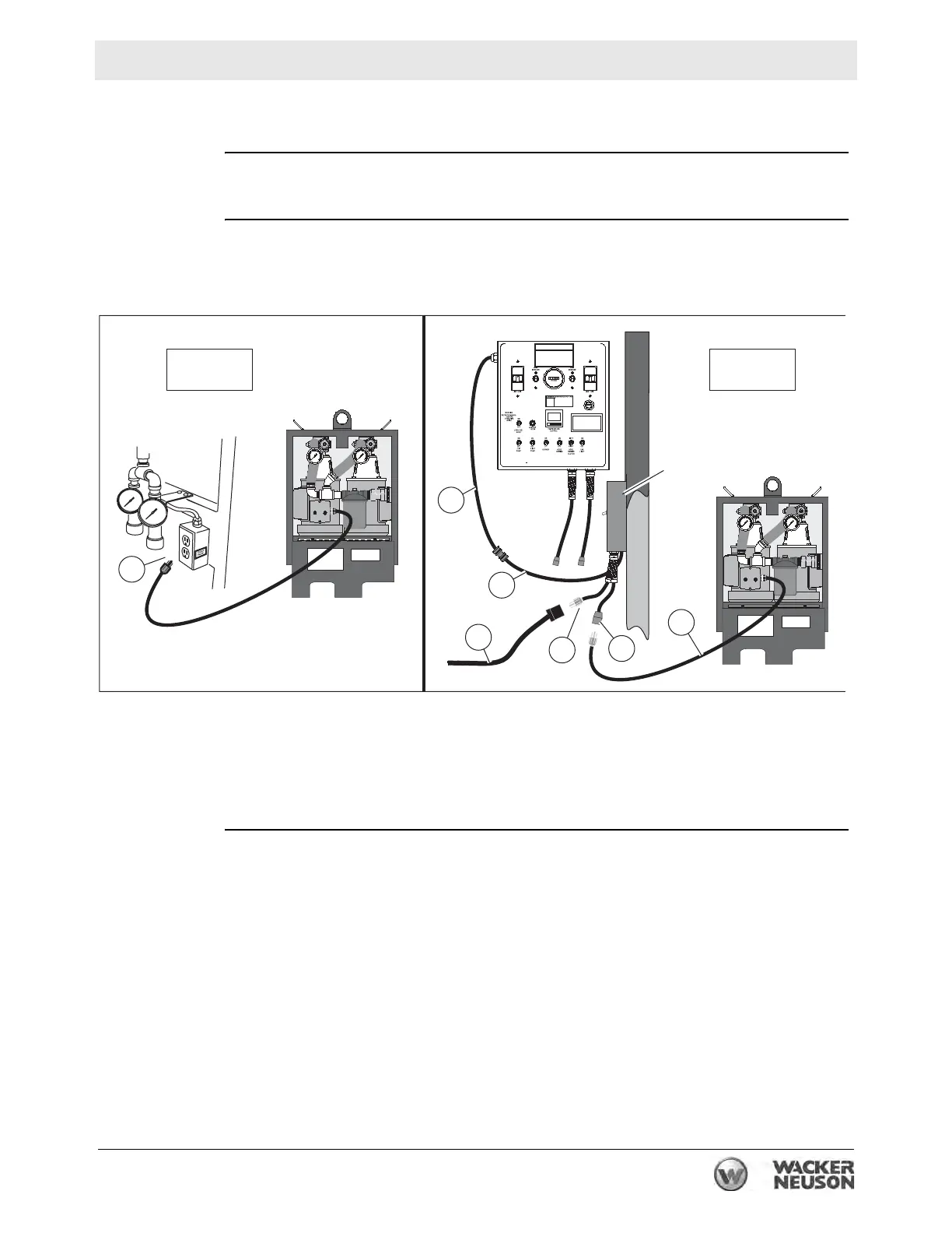
Make the following electrical connections.
1. Connect the power cord from the DPP1 (m) to the auxiliary receptacle labeled
“PUMP PACK”.
2. Connect the DIN leader (n) from the main control panel to the corresponding
DIN leader on the APP (o).
3. Connect a properly-rated extension cord (p) to the power cord (q) on the APP.
4. Connect the Pump Pack power cord (s) to the APP power adapter (r).
Operating
1. Start the parent machine. Turn on the burner and the pumps.
2. Place the ON-OFF switch of the APP in the ON position.
3. Start the pumps of both DPPs, one at a time.
4. Monitor the HTF flows, pressures, and temperature as the machine operates.
wc_gr008072
m
wc_gr00807
DPP1
APP
DPP2
m
n
o
p
q
r
s