GP Repair Maintenance
wc_tx000546gb.fm 63
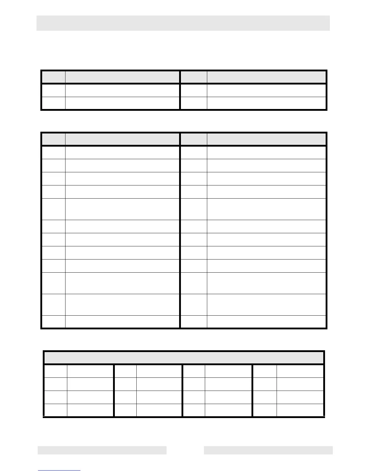
4.28 Components (CAN)—GP/GPS 5600A/6600A (rev. > 103)
Ref. Description Ref. Description
A Generator C Engine
B Control box D Electric start engines
Ref. Description Ref. Description
1 Main stator winding 1 13 Rectifier
2 Main stator winding 2 14 Rotor winding/brushes
3 Auto idle unit 15 Secondary (excitation) winding
4 Main circuit breaker 16 DC winding
5 Voltage selector switch
(120/240V position shown)
17 Automatic voltage regulator (AVR)
6 Duplex receptacle—120V 18 15A fuse (GPS only)
7 Twist-lock receptacle—120V 19 Ignition switch (GPS only)
8 Twist-lock receptacle—120/240V 20 GFCI
9 Auto idle switch 21 20A circuit breaker
10 5A fuse 22 20A circuit breaker
(GP 3800 CAN only)
11 Capacitor 23 30A circuit breaker
(GP 5600/6600 CAN only)
12 Engine ON / OFF switch 24 Neutral bond wire
Wire Colors
B Black R Red Y Yellow Or Orange
G Green T Tan Br Brown Pr Purple
L Blue V Violet Cl Clear Sh Shield
P Pink W White Gr Gray LL Light blue