GP Repair Troubleshooting
wc_tx000548gb.fm 77
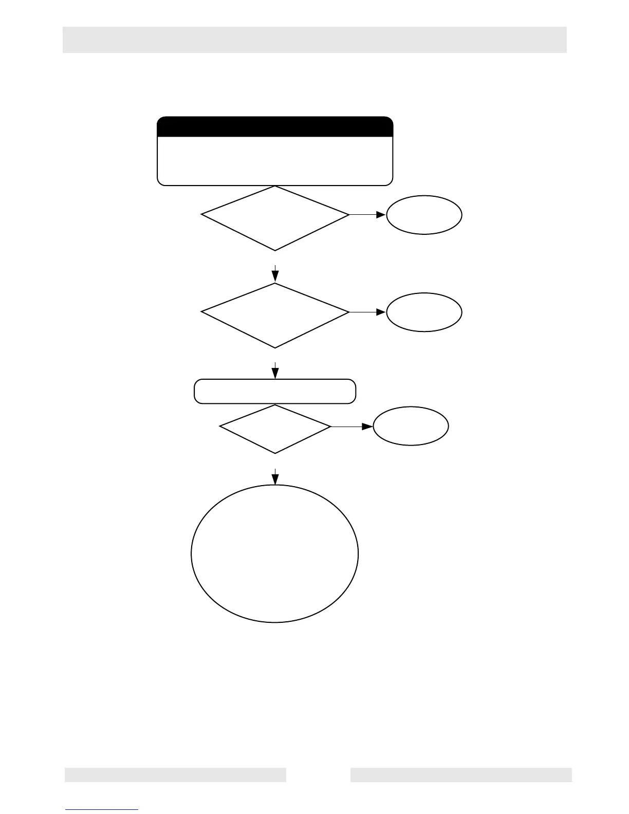
6.7 No Voltage at Receptacles—Flowchart 1B
Checking main and rotor windings
Measure the resistance values of the main windings
by measuring across R & Y (main 2); B & G (main 1).
For GP 2500A models, measure between R &W for
(main 2); Br & L (main 1).
Is the
correct value
measured for main
winding 2?
Replace
the stator.
Ye s
No
wc_gr003111
Is the
correct value
measured for main
winding 1?
Replace
the stator.
Ye s
No
Check resistance of rotor winding.
Is
correct resistance
measured?
Ye s
No
Replace
the rotor.
If both the rotor and
stator windings are OK, it
is impossible to have a
no-voltage condition at the
generator terminals.The
problem is in the circuitry
to the receptacles.
See Flowchart 1C.