Theory of Operation GP Repair
wc_tx000547gb.fm 70
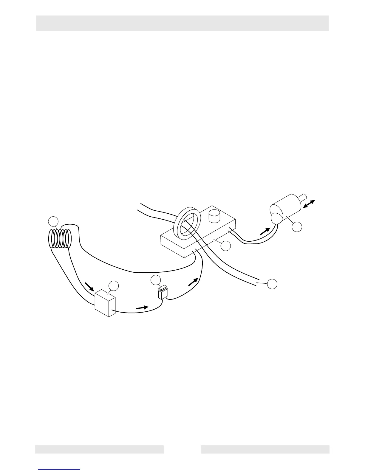
5.4 Auto Idle Circuit
See Graphic: wc_gr003120
The auto idle circuit consists of the DC winding (a), the rectifier (b), the
5A fuse (c), the auto idle unit (d), main output wires (which serve as
sensing wires for the auto idle circuit) (e), and the idle solenoid (f).
AC voltage induced in the DC winding is sent to the rectifier where it is
rectified to DC. This DC voltage is then sent to the auto idle unit.
through the 5A fuse. The auto idle unit senses the load on the
generator via two wires connected to the main windings. When no load
is sensed, the auto idle unit sends DC voltage to the idle solenoid; the
solenoid energizes and the throttle is pulled in to the slow position.
When a load is sensed by the auto idle unit, no DC voltage is sent to
the idle solenoid; the solenoid de-energizes and the throttle takes the
fast position.
e
d
a
DC+
DC+
DC
AC
wc_gr003120
b
c
f