Troubleshooting GP Repair
wc_tx000548gb.fm 78
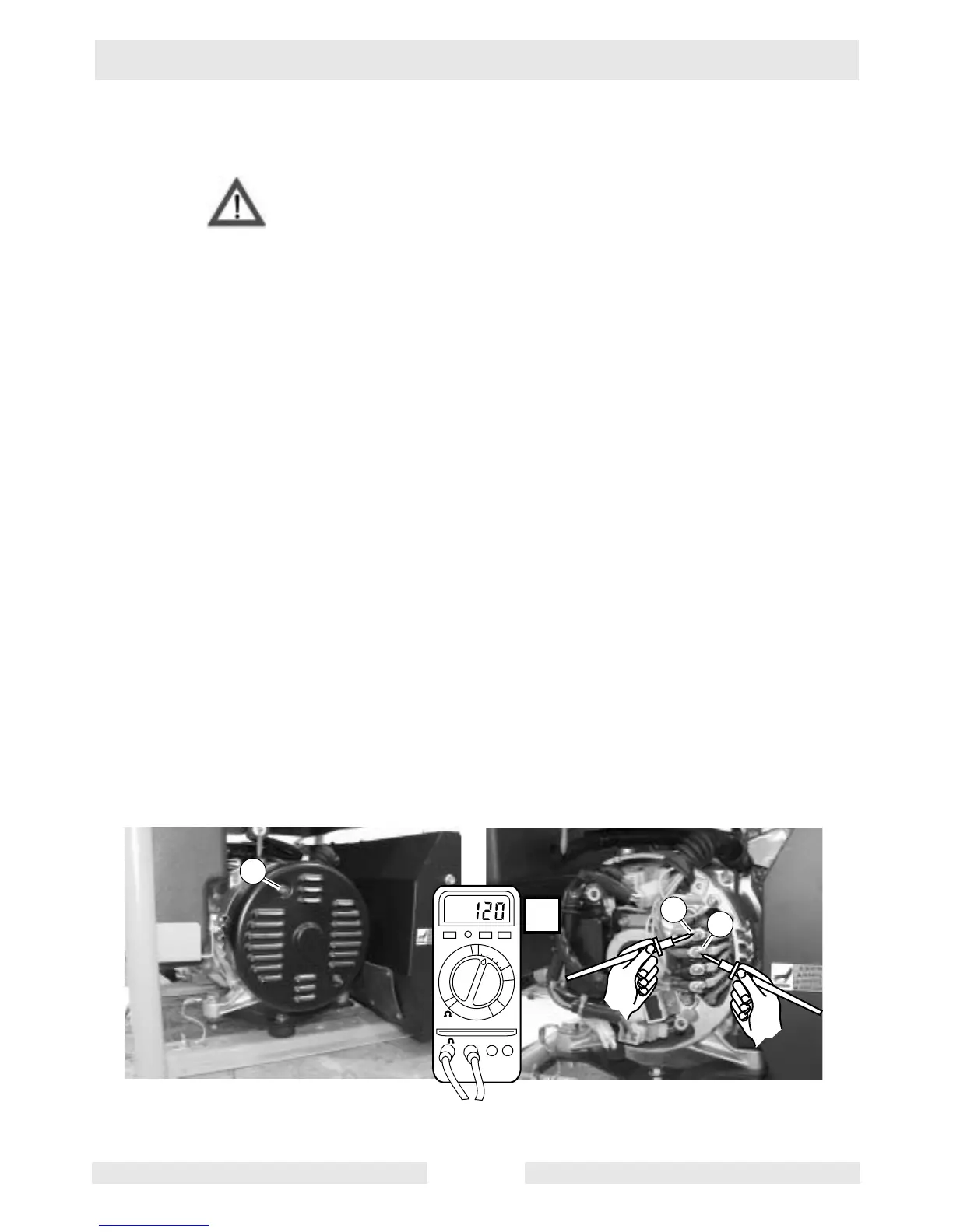
6.8 Checking Voltage at Generator Terminal Strip
See Graphic: wc_gr003122
Electric shock hazard. Only qualified personnel should conduct this
test.
By starting the troubleshooting procedures at the generator output
terminal strip you can determine whether the problem lies within the
generator or the circuit supplying the receptacles. To check the voltage
at the terminal strip, carry out the following procedures:
6.8.1 Remove the two screws (a) that secure the end cover to the generator
and remove the end cover.
6.8.2 Start the engine.
6.8.3 Using the AC voltage setting on the multimeter, measure the voltage
between the wire with the yellow marking (b) and the wire with the red
marking (c). There should be 120V±10%.
• If zero (0) volts is measured, it indicates a problem with main
winding 2 or the rotor winding.
• If 120V±10% is measured, main winding 2 and the rotor are func-
tioning; continue.
6.8.4 Using the AC voltage setting on the multimeter, measure the voltage
between the wire with the green marking and the wire with the black
marking. There should be 120V±10%.
• If zero (0) volts is measured, it indicates a problem with main
winding 1.
• If 120V±10% is measured, main winding 1 and the rotor are func-
tioning; any problems with the receptacles receiving voltage are
in the circuit to the receptacles.
WARNIN