Do you have a question about the Wali CS201 and is the answer not in the manual?
Use a stud finder to locate stud edges and mark the centerline for mounting holes.
Drill pilot holes and secure the wall plate level to the stud using screws.
Mark wall for holes, pre-drill with an 8mm bit, and insert concrete anchors.
Attach the wall plate to the wall using screws, ensuring it is level.
Attach the connect piece to the glass holder using two screws.
Insert glass holder into wall plate rail and tighten screws with Allen key.
Insert decorative covers at the top and bottom of the wall plate.
Loosen screws, adjust holder height, and retighten screws.
Place glass shelf on holders, attach with screw and bush, and tighten.
Insert cable into clip openings and attach the clip to the main pole.
Periodically check that screws are secured for safe use.
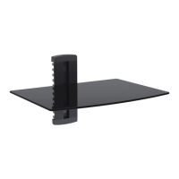
This document outlines the installation and features of a wall-mounted DVD shelf, designed to securely hold a DVD player or similar equipment. The device is primarily intended for indoor use and offers a clean, organized solution for managing media components.
The core function of this device is to provide a stable, wall-mounted platform for a DVD player or other small electronic devices, such as cable boxes or streaming devices. It consists of a wall plate that attaches to either wood studs or solid brick/concrete walls, two glass holders that connect to the wall plate, and a glass shelf that rests on these holders. The design aims to elevate the device, freeing up floor or cabinet space and contributing to a minimalist aesthetic. An integrated cable management system helps to conceal wires, maintaining a tidy appearance.
Installation Versatility: The device is designed for installation on two primary wall types:
Adjustable Height: A key feature is the ability to adjust the height of the glass holders. After the initial installation of the wall plate, the glass holders are inserted onto the wall plate rail. Users can loosen two screws with a 3mm Allen key (without removing them) to slide the glass holder up or down to their desired height. Once the optimal position is found, the screws are tightened to secure the holder. This flexibility allows users to customize the shelf's placement according to their specific needs and the layout of their entertainment setup.
Secure Shelf Attachment: The glass shelf is placed gently onto the glass holders. It is then attached to the glass holders using screws and plastic bushes. While the screws are initially tightened with a 3mm Allen key, they should not be fully tightened at this stage. The shelf is then centered over the holes, and the screws are securely tightened to ensure stability.
Cable Management System: To maintain a neat and organized appearance, the device includes a cable management system. After placing the DVD player on the mounted glass shelf, users can pull out a cable clip. Cables are inserted into any opening of the clip, with one end of the cable secured within it. The clip is then inserted into the main pole of the device. The other end of the cable can be routed out from another opening of the clip, and the clip is pushed fully into the main pole until it is flush. This system effectively hides unsightly wires, contributing to a cleaner entertainment area.
Decorative Elements: Two decorative covers are provided for the top and bottom of the wall plate, along with two plastic covers, to enhance the aesthetic integration of the device with the wall.
Regular Security Checks: To ensure ongoing safety and stability, it is recommended that users periodically check the security of the mounted DVD bracket. Specifically, the screws should be checked every two months to confirm they remain fixed well and have not loosened over time. This proactive measure helps prevent potential issues and ensures the device continues to function safely.
Firm but Not Overtightened Screws: During installation, it is crucial to tighten screws firmly but avoid overtightening. Overtightening can damage the components, which could significantly reduce their holding power and compromise the device's stability. This instruction serves as a maintenance guideline to ensure the longevity and reliability of the installation.
Consultation for Doubts: If users have any doubts or questions regarding the installation or ongoing maintenance, they are advised to consult their retailer or the service department for detailed assistance. This ensures that any concerns are addressed by professionals, preventing potential damage or unsafe conditions.
Indoor Use Only: The product is explicitly designed for indoor use. Using it outdoors could lead to product failure and potential personal injury due to exposure to elements not accounted for in its design. This is a critical maintenance and safety instruction.
| Material | Steel |
|---|---|
| Adjustable Height | No |
| Color | Black |
| Weight Capacity | Up to 100 lbs per shelf |
| Mounting Type | Freestanding |
| Finish | Powder Coated |