Assembly Instructions
26
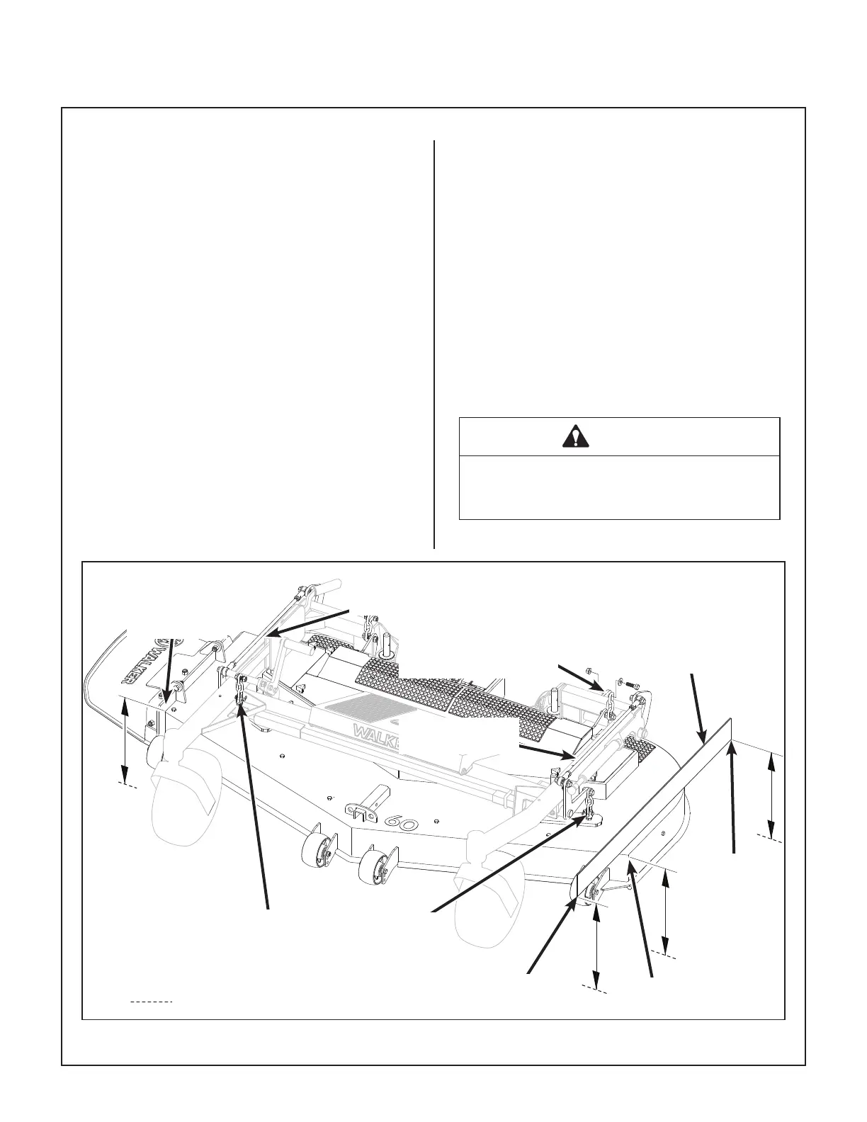
DS60-3 Deck Leveling
The mower deck and support frame are jig welded
and the deck support linkage is factory adjusted.
Within normal tolerances, very little, if any, adjust-
ment should be required to level the deck. Tire size
and pressure will aect the levelness of the deck.
Assure that all tires (tractor and deck caster
wheels) are properly inated prior to checking
deck levelness or performing the deck leveling
procedure.
Measuring Deck Levelness
1. Position the mower on a smooth, level surface,
and set the deck height to the most common
cutting position. Refer to ADJUSTING CUT-
TING HEIGHT in Operating Instructions.
2. See the DS60-3 Deck Leveling illustration for
side-to-side and front-to-back deck level mea-
surement points. Side-to-side measurements
should not vary more than 1/8 in. (3 mm). Front-
to-rear measurements should have the rear 1/4
in. (6 mm) to 3/8 in. (10 mm) higher than the
front. If either set of measurements are not
within tolerance, perform the Deck Leveling Pro-
cedure.
Deck Leveling Procedure
1. Position the mower on a smooth, level surface,
and set the deck height to the most common
cutting position. Refer to ADJUSTING CUT-
TING HEIGHT in Operating Instructions.
WARNING
The machine must be shut o during this
procedure.
DS60-3 Deck Leveling
Ground
Approx. 36 in. (914 mm)
Long Straight Edge
Right Height
Adjustment Rod
Rear
Measurement
Point
Left Side
Measurement Point
Right Support
Chain Clevis
Left Support
Chain Clevis
Left Height
Adjustment Rod
Front
Measurement Point
Left Rear Deck Support
Chain (Remove Upper
Bolt for Leveling)
Right Side
Measurement
Point