Assembly Instructions
21
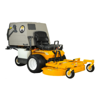
Mower Deck Assembly
CAUTION
The engine must be o during the tractor
assembly and deck installation.
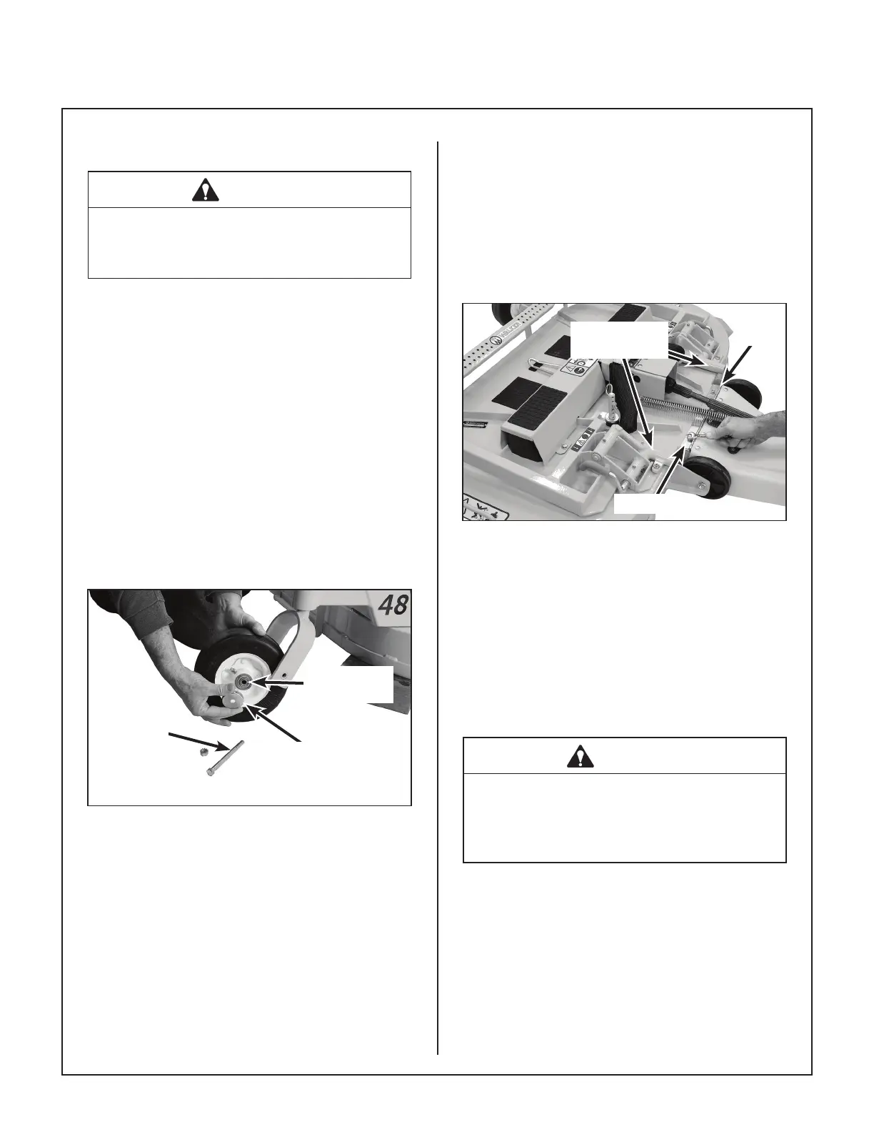
Deck Caster Wheels Installation
1. Remove the bolt and nut from each deck caster
wheel fork.
2. Fit a bearing cup on the outside of each wheel
bearing and slide the wheel assembly into the
wheel fork.
3. Insert the 3/8-16 x 4-1/2 in. bolt through the
wheel fork with the bolt head to the outside and
install the 3/8-16 Keps nut.
4. Tighten the bolt and nut until the axle spacer
tube and inner bearing race bottom against the
inside of the wheel fork (will not turn) while the
wheel spins freely without binding.
Axle Bolt
Axle Spacer
Tube
Bearing
Cup
Deck Caster Wheel Installation
5. Grease the caster wheel bearings and caster
pivot bearings—two (2) grease ttings for each
wheel.
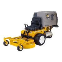
Deck Discharge Chute Installation
(GHS Collection Models Only)
Mount the discharge chute hinge on top of the deck
discharge opening using two (2) 1/4-20 x 1/2 in. car-
riage bolts and 1/4-20 ESNA nuts. Position the bolts
with the heads inside the chute and the nuts on the
outside. Attach spring for tilt-up action from chute to
bracket on deck.
Attach
Chute
Nut on Top
Carrier Frame
Tube Sockets
Discharge Chute Installation
on Collection Deck
Deck Discharge Deector Shield Installation
(Side Discharge Models Only)
Attach the side discharge deector shield using two
(2) 3/8-16 x 1-1/4 in. bolts, 3/8-16 ESNA nuts, and
3/8 in. wave spring washers. The wave washers t
between the two hinging surfaces. Tighten the nuts
until the shield moves freely but is not loose.
WARNING
DO NOT operate the machine without the
grass deector shield attached and in the
lowest possible position.