Operating Instructions
36
Water Temperature Warning Light/Horn
The water temperature warning light and horn indi-
cate that engine coolant temperature is above the
safe operating limit and the engine is overheating.
If this light comes on, there may be a problem with:
● Radiator cooling air ow (material packed into
radiator cooling ns, clogged air intake screen)
● Low coolant quantity in cooling system
● Engine alternator belt
● Thermostat function
● Cooling fan not operating
Stop the engine and correct the source of the prob-
lem before further operation.
IMPORTANT: Continued operation of the engine
with an illuminated water temperature warning light
MAY result in severe engine damage.
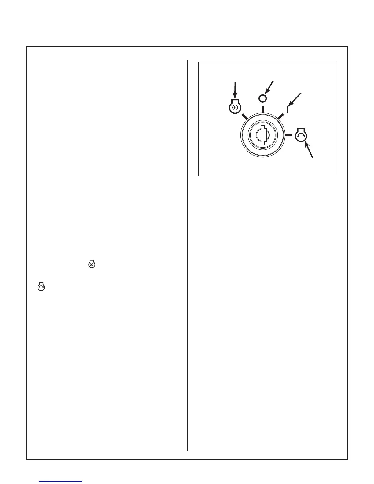
Ignition Switch
The ignition switch is used to start and stop the en-
gine (and preheat the diesel engine). The switch
has four positions: is the glow plug preheat posi-
tion, “O” is the OFF position, “I” is the ON (RUN)
position that the key returns to after starting, and
is the START position. When starting the engine,
turn the key clockwise to the START position. Do
not hold the key in the START position longer than
10 seconds. If the engine does not start, return the
key to the “O” position for at least 60 seconds before
making a restart attempt. Prolonged cranking can
damage the starter motor and shorten battery life.
Release the key when the engine starts, and it will
return to the ON (RUN) position. To stop the engine,
rotate the key counterclockwise to the “O” position.
NOTE: When starting the engine, turn and hold the
ignition key in the glow plug preheat position. The
time required is approximately 10 to 30 seconds,
depending on engine temperature. Refer to START-
ING THE ENGINE in this section.
OFF
START
Glow Plug Preheat
ON (RUN)
Ignition Switch
Light Switch (For Optional Lights)
Operates headlights (when installed).
Warning Horn
The warning horn sounds to alert the operator that
an unsafe engine condition is being indicated—
when engine coolant temperature is too high or en-
gine oil pressure is too low. If the horn sounds, check
the indicator lights and correct the problem before
further operation.
Circuit Breakers
Two manual reset circuit breakers are located on
the instrument panel. Each has a button that pops
out if the circuit breaker trips. The 10 amp circuit
breaker protects the circuits to the (optional) head-
lights and fuel pump. The 7 amp circuit breaker pro-
tects the instrument panel circuits to the meters,
warning lights and warning horn, plus the safety
switch circuits, fuel valve solenoid, and the GHS. In
addition, both an auto-reset 30 amp circuit breaker
protecting the radiator cooling fan system and an
auto-reset 40 amp master circuit breaker are mount-
ed near the battery.