Assembly Instructions
23
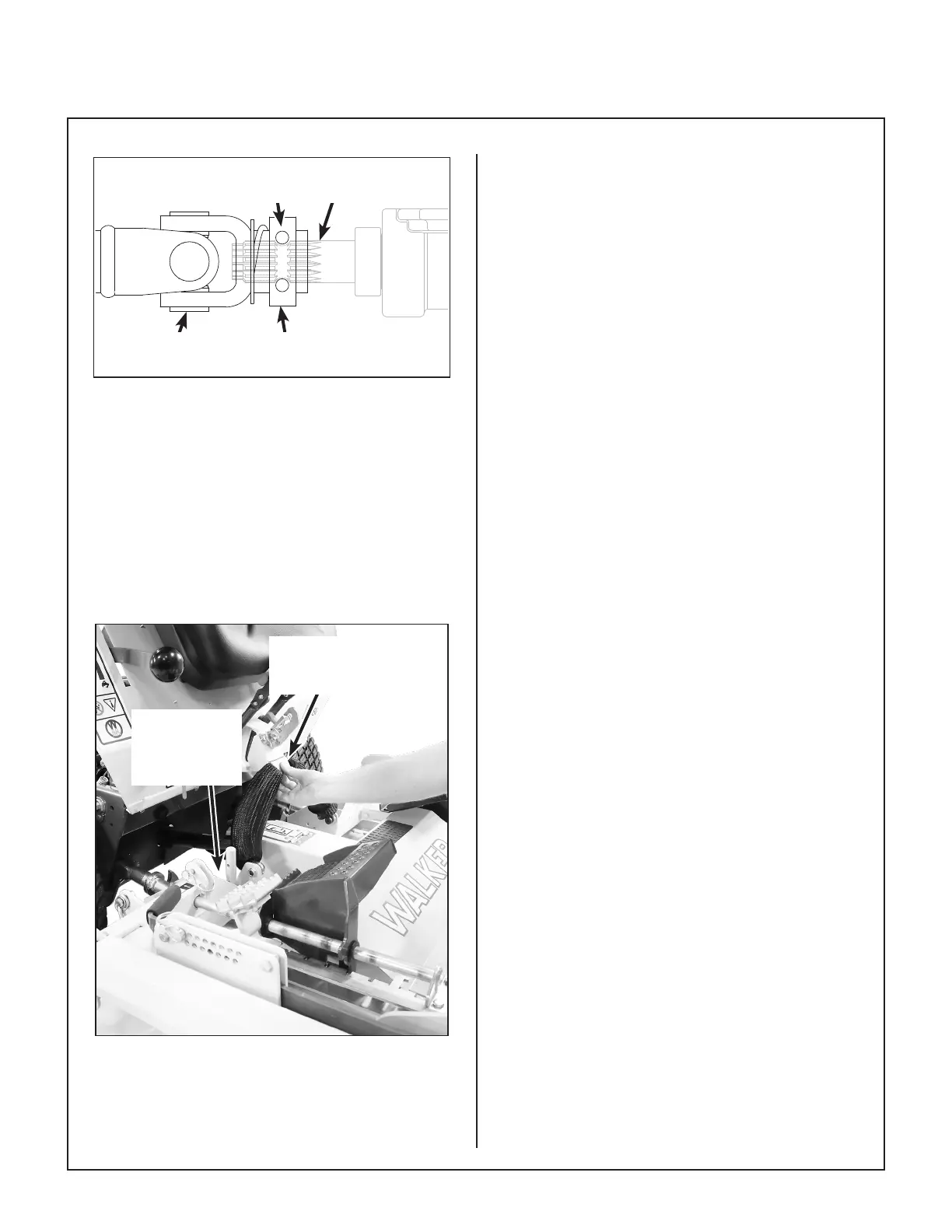
Coupler Ring in
Locked Position
PTO Drive
Shaft
PTO Coupler
UJoint
Internal Balls
Locked on Shaft
Quick Disconnect Ring “Locked” Position
7. Raise the mower body (instead of lifting the front
of deck) and clip the counterweight springs to
the receptacle on front of body. Lower the body
to tension the springs. (Refer to Deck Counter-
weight Spring Installation photo.)
8. With the counterweight springs connected, the
weight on the deck caster wheels should be
190 to 230 Ib (86.2 to 104.3 kg); this adjustment
is preset at the factory.
Counterweight Springs
Clip Onto Body
With Body Tilted Up
Lynch Pins
Lock Deck on
Support Arms
(Not Visible)
Deck Counterweight Spring Installation
Deck Leveling
The mower deck and support frame are jig welded
and the deck support linkage is factory adjusted.
Within normal tolerances, very little, if any, adjust
ment should be required to level the deck. Tire size
and pressure will affect the levelness of the deck.
Assure that all tires (tractor and deck caster
wheels) are properly inated prior to checking
deck levelness or performing the deck leveling
procedure.
Measuring Deck Levelness
1. Position the mower on a smooth, level surface,
and set the deck height to the most common
cutting position. Refer to ADJUSTING CUT-
TING HEIGHT in Operating Instructions.
2. See the Deck Leveling illustration for sideto
side and fronttoback deck level measurement
points. Sidetoside measurements should not
vary more than 1/8 in. (3 mm). Fronttorear
measurements should have the rear 1/4 in.
(6 mm) to 3/8 in. (10 mm) higher than the front.
If either set of measurements are not within
tolerance, perform the Deck Leveling Procedure.