Front
Cr
()
0
0.°
0 o
IL
[
0
0
11-
04‘
Back
o o
0
e
irLial;
0
Not
used
5V
AUX1
AUX2
AUX3
AILE
THRO
ELEV
RUDD
EAR
0
.0.
r
i2=ZE.T
Quick Start Guide
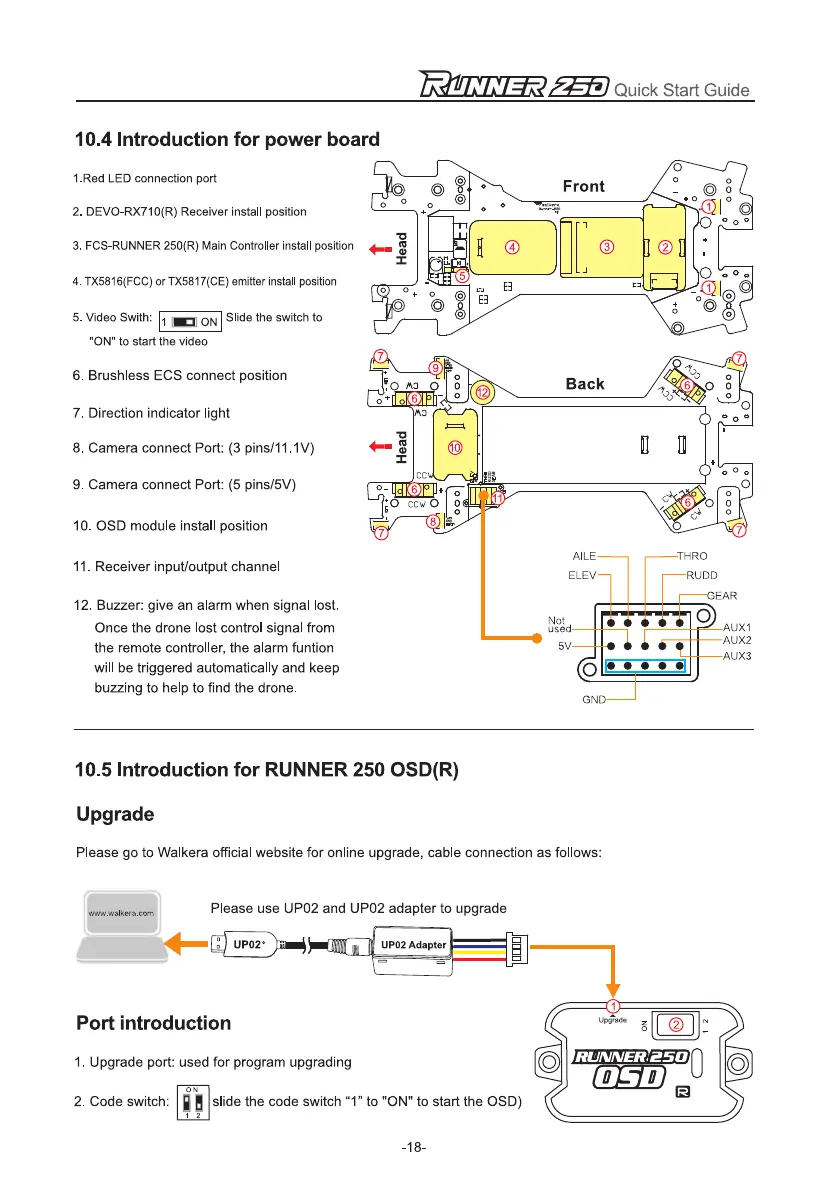
10.4 Introduction for power board
1.Red LED connection port
2.
DEVO-RX710(R) Receiver install position
3.
FCS-RUNNER 250(R) Main Controller install position
4.
TX5816(FCC) or TX5817(CE) emitter install position
5.
Video Swith: 1
ON Slide the switch to
ON to start the video
6.
Brushless ECS connect position
7.
Direction indicator light
8.
Camera connect Port: (3 pins/11.1V)
9.
Camera connect Port: (5 pins/5V)
10.
OSD module install position
11.
Receiver input/output channel
12.
Buzzer: give an alarm when signal lost.
Once the drone lost control signal from
the remote controller, the alarm funtion
will be triggered automatically and keep
buzzing to help to find the drone.
10.5 Introduction for RUNNER 250 OSD(R)
Upgrade
Please go to Walkera official website for online upgrade, cable connection as follows:
Please use UP02 and UP02 adapter to upgrade
www.walkera.corn
UP02°
II
rt
UP02 Adapter
Port introduction
1.
Upgrade port: used for program upgrading
ON
2.
Code switch:
slide the code switch "1" to "ON" to start the OSD)
-18-