Walther Systemtechnik GmbH – D 76726 Germersheim
Telefon: +49 (0)7274-7022-0 Telefax: +49 (0)7274-7022-91
http://www.walther-2000.de – info@walther-2000.de
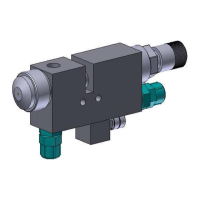
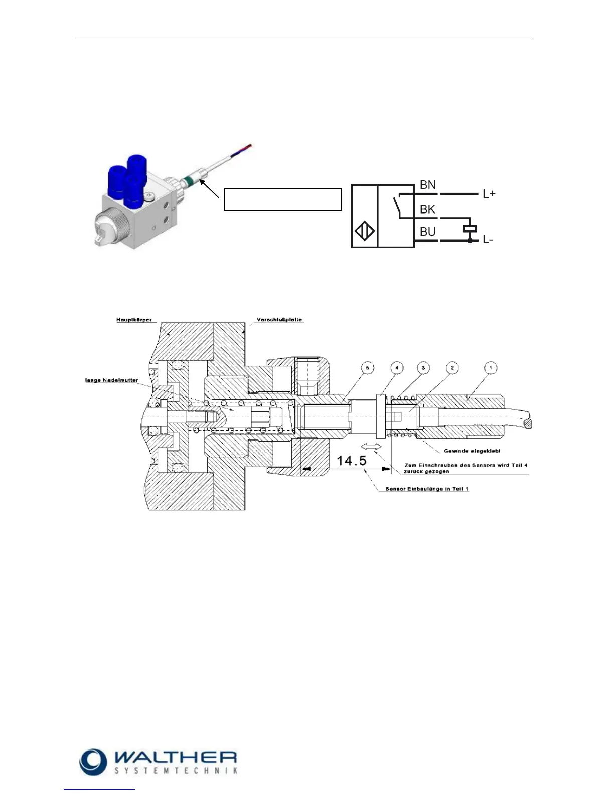
5.1 Raster-Needle Sensor
Optionally, you can use a raster-needle lock with a pre-installed, inductive proximity switch. It will release a
signal when the needle piston with the needle is open. This will help you in digitally monitoring the status
„nozzle open“.
.
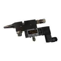
5.1.1 Setting of Sensor (Raster-Needle)
1. The screw-in sensor M4 x 0,5 (2) will be glued with a high-strength screw lock into the sensor holder
over a length of 14.5mm (1).
2. Screw in the regulating spindle (5) until the needle is closed and no more material is discharged from
the nozzle.
3. Connect the sensor to a control unit for adjusting.
4. Then slide the spring (3) and the spindle carrier (4) onto the sensor and together screw in into regu-
lating spindle until you receive a signal.
5. Open (unscrew) the regulating spindle until the signal stops (up to max. 8 steps). If the signal of the
sensor hasn’t stopped by then, use the spindle carrier of the sensor for fine-adjustment until the sig-
nal stops.
6. The spindle carrier has to be pushed backed against the spring for fine-adjustment so the sensor can
be turned in the regulating spindle until the signal stops.
 Loading...