Waltron User Manual 101-016-B.3
3041 Silica Analyzer
The sample drain of the analyzer must be at ambient
pressure with no restriction or counter pressure. Please
verify that this condition has been strictly respected during
installation.
Clearance requirements for the analyzer should be about 8” (20 cm) on either side and
about 40” (100 cm) in the front.
Sufficient space for the reagent containers should be provided on the side or beneath the
analyzer.
The reagent containers should be positioned in the reagent bracket or a suitable basin in
case of spills.
Respect the maximum height of 16” (40 cm) between the
reagent's bottle(s) and the reagent's pump(s).
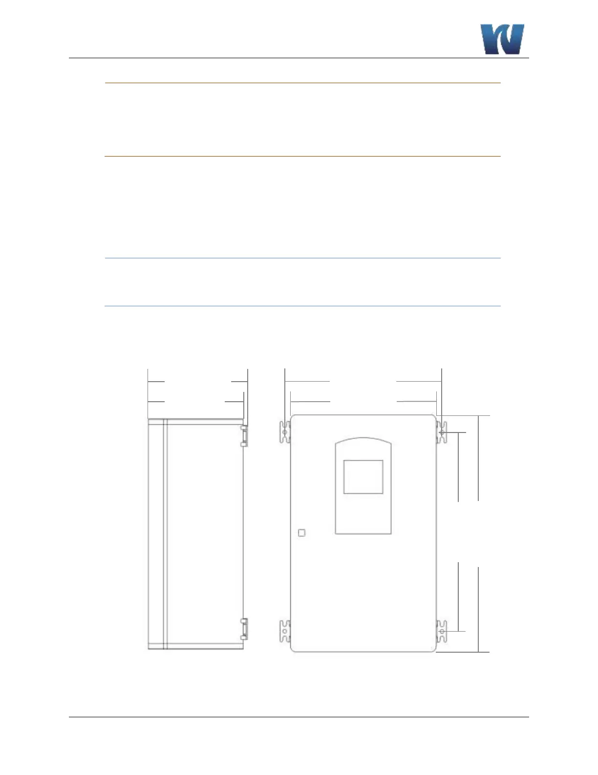
3.5 MOUTING SCHEMATICS
Figure 3.1: The dimensions for mounting the analyzer.
 Loading...