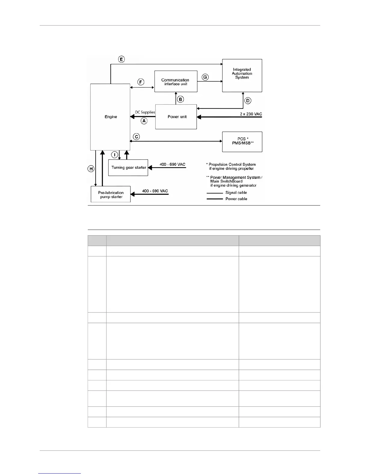
14.1.7 Cabling and system overview
Fig 14-3 UNIC overview
Table 14-1 Typical amount of cables
Cable types (typical)From <=> ToCable
2 x 4 mm
2
(power supply) *
2 x 4 mm
2
(power supply) *
2 x 4 mm
2
(power supply) *
2 x 4 mm
2
(power supply) *
2 x 4 mm
2
(power supply) *
2 x 4 mm
2
(power supply) *
2 x 4 mm
2
(power supply) *
2 x 4 mm
2
(power supply) *
Engine <=> Power UnitA
2 x 2.5 mm
2
(power supply) *Power unit => Communication interface unitB
1 x 2 x 0.75 mm
2
1 x 2 x 0.75 mm
2
1 x 2 x 0.75 mm
2
24 x 0.75 mm
2
24 x 0.75 mm
2
Engine <=> Propulsion Control System
Engine <=> Power Management System / Main Switch-
board
C
2 x 0.75 mm
2
Power unit <=> Integrated Automation SystemD
3 x 2 x 0.75 mm
2
Engine <=> Integrated Automation SystemE
1 x Ethernet CAT 5Engine => Communication interface unitF
1 x Ethernet CAT 5Communication interface unit => Integrated automation
system
G
2 x 0.75 mm
2
Engine => Pre-lubrication pump starterH
1 x CAN bus (120 ohm)Engine => Turning gear starterI
14-4 DBAE248994
Wärtsilä 31DF Product Guide14. Automation System
 Loading...


