The fuel gas can typically be contained as CNG, LNG at atmospheric pressure, or pressurized
LNG. The design of the external fuel gas feed system may vary, but every system should
provide natural gas with the correct temperature and pressure to each engine.
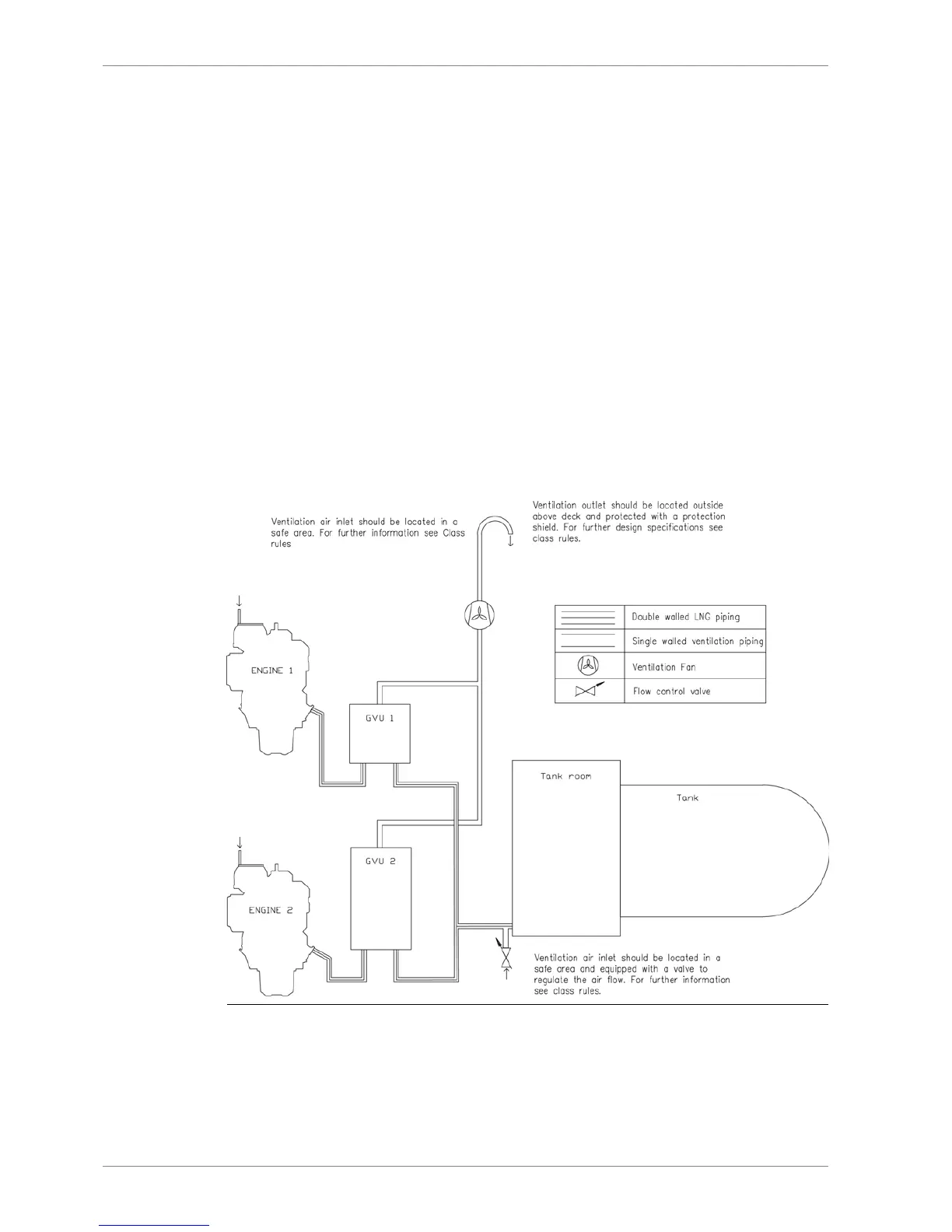
6.3.1.3 Double wall gas piping and the ventilation of the piping
The annular space in double wall piping is ventilated artificially by underpressure created by
ventilation fans. The first ventilation air inlet to the annular space is located at the engine. The
ventilation air is recommended to be taken from a location outside the engine room, through
dedicated piping. The second ventilation air inlet is located at the outside of the tank connection
space at the end of the double wall piping. To balance the air intake of the two air intakes a
flow restrictor is required at the air inlet close to the tank connection space. The ventilation
air is taken from both inlets and lead through the annular space of the double wall pipe to the
GVU room or to the enclosure of the gas valve unit. From the enclosure of the gas valve unit
a dedicated ventilation pipe is connected to the ventilation fans and from the fans the pipe
continues to the safe area. The 1,5 meter hazardous area will be formed at the ventilation air
inlet and outlet and is to be taken in consideration when the ventilation piping is designed.
According to classification societies minimum ventilation capacity has to be at least 30 air
changes per hour. With enclosed GVU this 30 air changes per hour normally correspond to
-20 mbar inside the GVU enclosure according to experience from existing installations. However,
in some cases required pressure in the ventilation might be slightly higher than -20 mbar and
can be accepted based on case analysis and measurements.
Fig 6-3 Example arrangement drawing of ventilation in double wall piping system
with enclosed GVUs (DBAC588146)
6-12 DBAE248994
Wärtsilä 31DF Product Guide6. Fuel Oil System
 Loading...


