In electric propulsion applications loading ramps are implemented both in the propulsion control and in the
power management system, or in the engine speed control in case isochronous load sharing is applied.
When the load sharing is based on speed droop, it must be taken into account that the load increase rate
of a recently connected generator is the sum of the load transfer performed by the power management
system and the load increase performed by the propulsion control.
Maximum instant load steps
The electrical system must be designed so that tripping of breakers can be safely handled. This requires
that the engines are protected from load steps exceeding their maximum load acceptance capability. If
fast load shedding is complicated to implement or undesired, the instant load step capacity can be increased
with a fast acting signal that requests transfer to diesel mode.
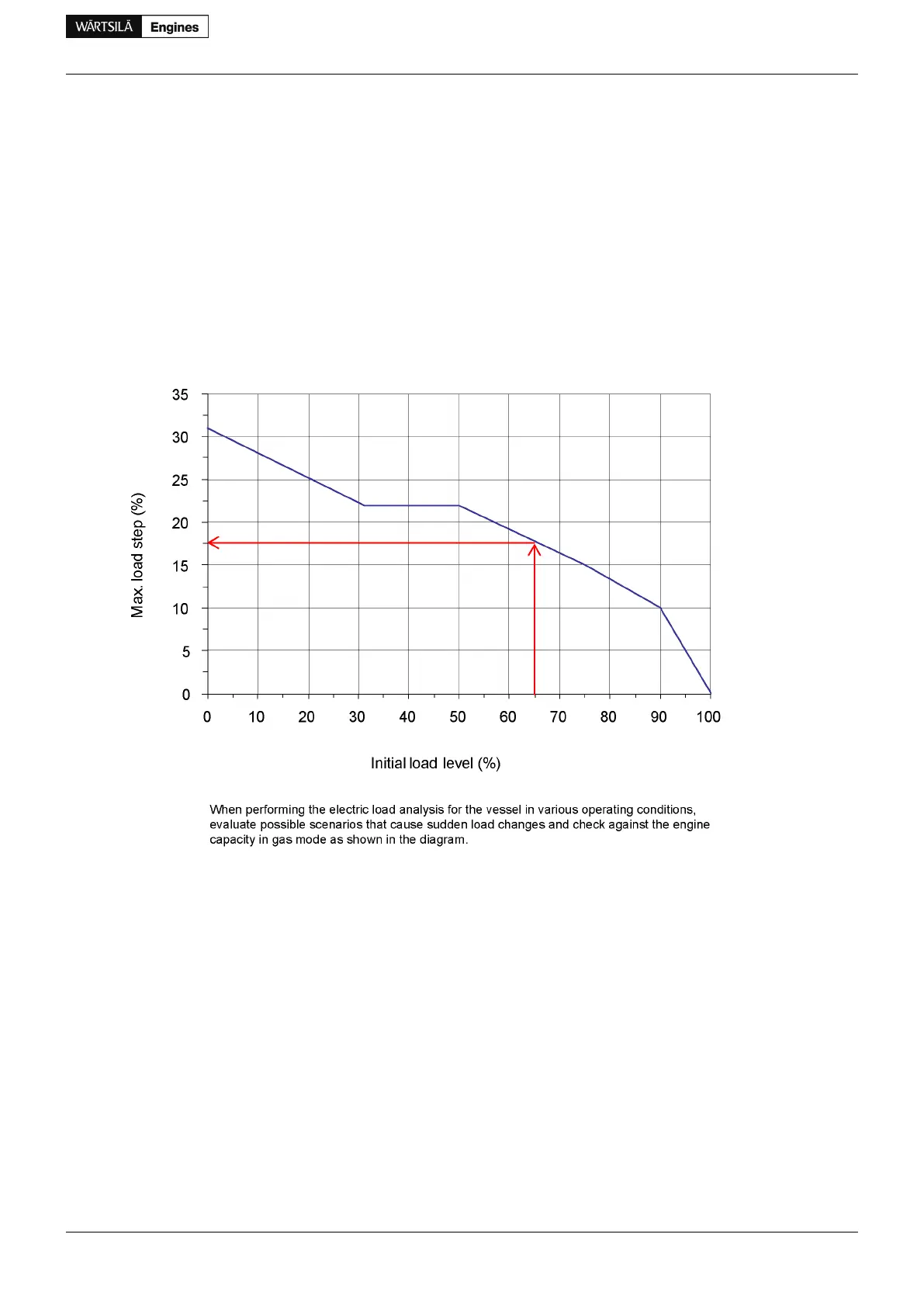
Gas mode
Figure 2.4 Maximum instant load steps in % of MCR in gas mode
• Maximum step-wise load increases according to figure
• Steady-state frequency band ≤ 1.5 %
• Maximum speed drop 10 %
• Recovery time ≤ 10 s
• Time between load steps of maximum size ≥ 15 s
• Maximum step-wise load reductions: 100-75-45-0%
Diesel mode
• Maximum step-wise load increase 33% of MCR
• Steady-state frequency band ≤ 1.0 %
• Maximum speed drop 10 %
• Recovery time ≤ 5 s
• Time between load steps of maximum size ≥ 8 s
Product Guide Wärtsilä 34DF - 3/2012 11
Product Guide
2. Operating Ranges
 Loading...


