Unit components:
Solenoid valveCV-V0#Gas control valveV06Manual shut off valveV01
Inerting valveV07Vent valveV02
Sensors and indicators
Pressure transmitter, inert gasP05Pressure transmitter, gas inletP01
Pressure transmitter, control airP06Pressure manometer, gas inletP02
Pressure transmitterP07Pressure transmitterP03
Temperature sensor, gas inletT01Pressure transmitter, gas outletP04
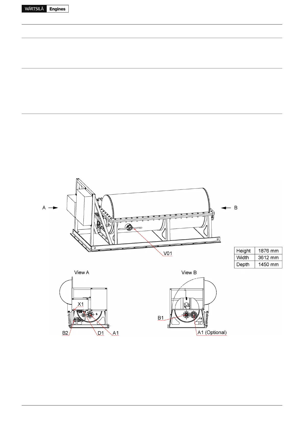
StandardPressure classSizePipe connections
ISO 7005-1DN16DN80Gas inlet [5-10 bar(g)]A1
ISO 7005-1DN16DN80Optional gas inlet / Air inletA1'
ISO 7005-1DN16DN80Gas outletB1
DIN 2353DN16G1/2 ' 'Inert gas [max 15 bar(g)]B2
DIN 2353DN16Gas ventingD1
DIN 2353G1/2 ' 'Instrument air [6-8 bar(g)]X1
Figure 6.5 Main dimensions of the GVU (DAAF020519)
Master fuel gas valve
For LNG carriers, IMO IGC code requires a master gas fuel valve to be installed in the fuel gas feed system.
At least one master gas fuel valve is required, but it is recommended to apply one valve for each engine
compartment using fuel gas to enable independent operation.
It is always recommended to have one main shut-off valve directly outside the engine room and valve room
in any kind of installation.
Product Guide Wärtsilä 34DF - 3/2012 47
Product Guide
6. Fuel System
 Loading...


