400 90145
25/02/2010
1-E
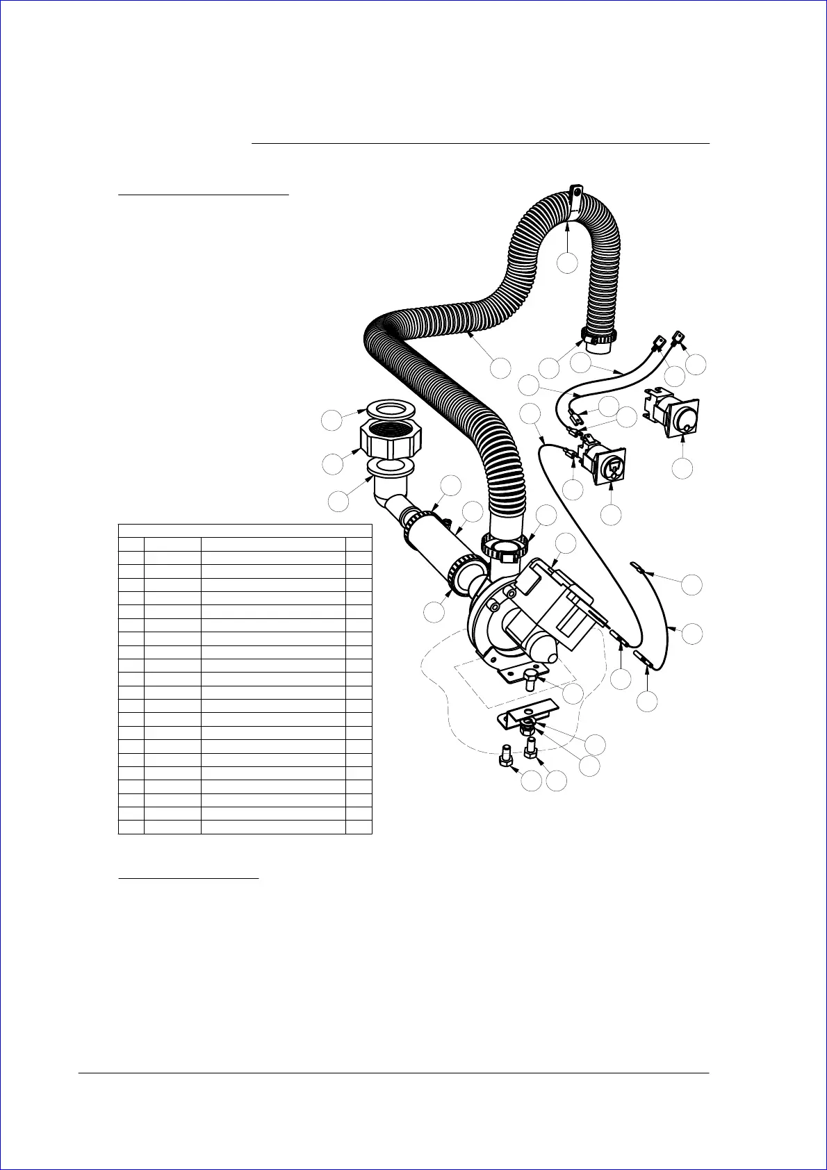
DRAIN PUMP KIT 0440032 - GL5/PW2(3)/PW3
REV
PARTS LIST - GL5 DRAIN PUMP KIT 0440032
QTYDESCRIPTION
PART NUMBERITEM
4HOSE CLAMP ASS161
1P CLIP600 301732
1
HOSE DRAIN 2.5M
600 601053
1DRAIN PUMP600 601024
1
GL5 DRAIN PUMP RETROFIT DIAGRAM
400 901455
3MS HX SS 304 M6 x 12884616
1
WASHER SPRING SS 304 1/4 inch (M6)
8566-17
1ASSY DRAIN SWITCH WITH SYMBOL400 101488
7
TERMINAL RED SPADE - 7H35609
1TERMINAL RED FLATH420710
1HOSE 22mm x 100mm6197-211
1
ELBOW DRAINC160204
12
1BACKNUT DRAIN WASTEC18010213
1
GASKET DRAIN WASTE
201014
1GL5 DRAIN PUMP MOUNT201 2007215
1HEX NUT M6810616
1SWITCH DRAIN 2P NO/NC 600 3021317
0.5mWIRE 0.75 RED600 3001518
1mWIRE 0.75 BLACK600 3001619
1mWIRE 0.75 YELLOW-BROWN600 3003220
0.5mWIRE 0.75 WHITE-BLUE600 3003321
GL5 RETROFIT INSTRUCTIONS
1. Attach drain pump mount bracket into base, using bolt #6, spring washer #7 and nut #16 supplied in kit.
2. Pre-assemble the drain pump with the flexible outlet hose #3, the inlet hose #11, the drain elbow #12 and the back nut #13. Secure the
hoses with the supplied hose clamps #1.
3. Push the drain pump into the base through the drain cutout in the base. 1. In this way the pump head will be located below the base that is
necessary for proper drain pump operation.
4. Fit the drain waste gasket #14 into the back nut #13, and screw the back nut #13 on to the drain waste of the machine.
5. Secure drain pump on mount bracket with bolts #6.
6. Connect Yellow-Brown and Black wires, supplied in a wiring loom, to the drain pump electrical connectors.
7. Cut off the hole in the control panel for drain switch #17.
8. Fit drain switch and connect it according to the wiring diagram using wires supplied in the loom.
9. Fit the drain hose support bracket #2, using the stud at the back of the cabinet and M5 nut, to support drain outlet hose above the water
level of the machine.
1
11
1
1
2
4
3
17
8
9
9
9
9
9
1
6
7
16
66
12
13
14
10
9
9
TO SELECTOR
SWITCH
TO POWER
TERMINAL
20
18
21
19
PW2/PW3 RETROFIT INSTRUCTIONS
1. Pre-assemble the drain pump with the flexible
outlet hose #3, the inlet hose #11, the drain elbow
#12 and the back nut #13. Secure the hoses with
the supplied hose clamps #1.
2. Secure drain pump on the front of the base with
M6 bolts #6, provided in the kit.
3. Fit the drain waste gasket #14 into the back nut
#13 and screw the back nut #13 on to the drain
waste of the machine.
4. Secure drain outlet hose above the water level
using P clip #2 supplied in the kit.
5. Cut out the right side hole below the wash
temperature gauge in the control panel label
(if see from the front) and fit the drain switch #8.
6. Wire the drain pump and the drain switch
according to electrical diagrams, provided in
service manual or schematic diagram, supplied
with the machine.
GL5 DRAIN
SWITCH
PW2/PW3 DRAIN
SWITCH