Watlow Series SD • 12 • Chapter 2 Install and Wire
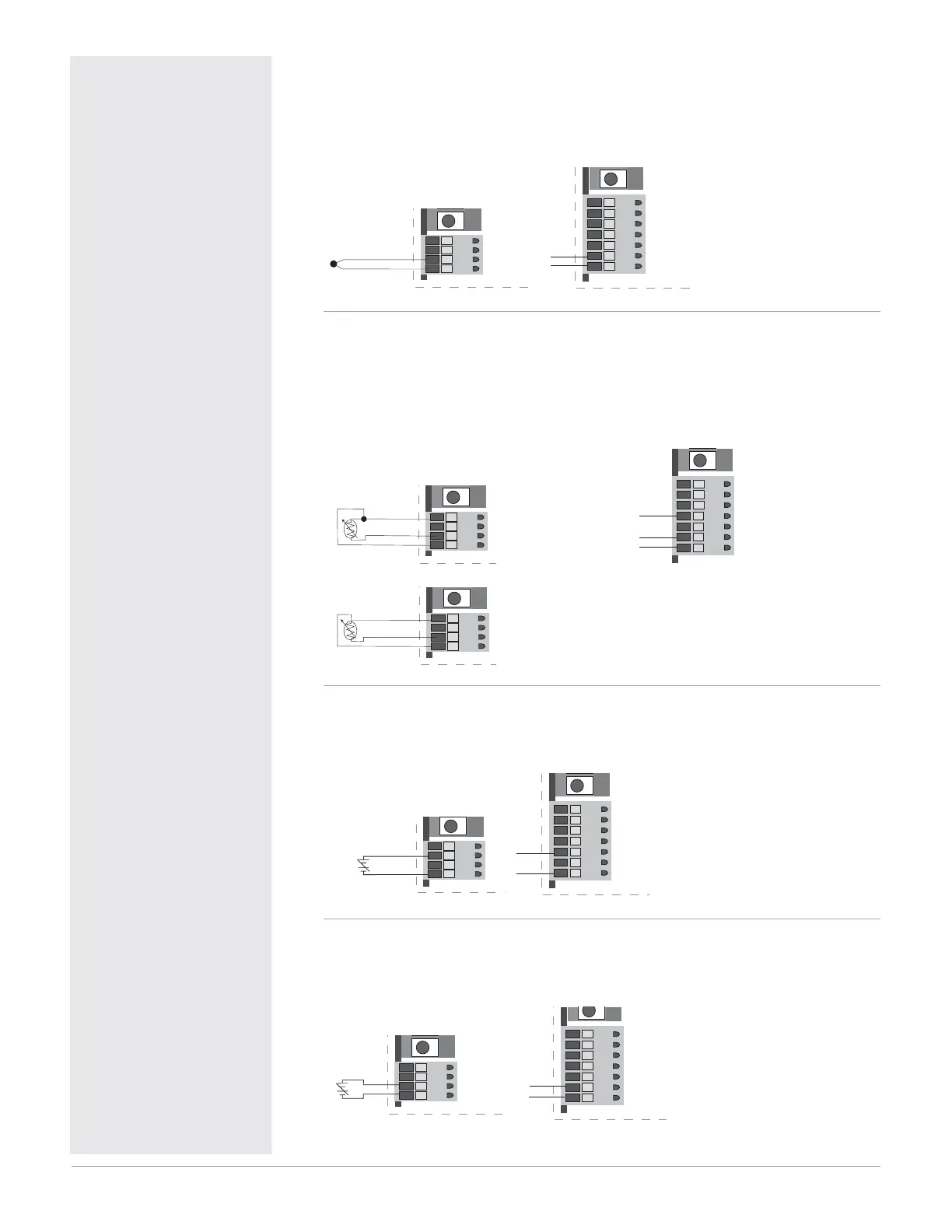
Figure 12a — Thermocouple Input
(all model numbers)
Thermocouples are polarity sensitive. The negative lead (usually red) must be
connected to terminal 11.
• Input impedance: >20 M
6
8
9
10 11
+10
-11
4
8
9
10
11
5
6
7
10
11
Figure 12b — RTD Input (100 Ω DIN curve 0.00385 Ω/Ω/°C)
(all model numbers)
Terminals 8 and 11 must be shorted for a two-wire RTD. For three-wire RTDs,
the S1 lead (usually white) must be connected to terminal 10.
• Nominal excitation current: 390µA
6
8
9
10 11
S1 10
11
S2 8
2-wire RTD
4
8
9
10
11
5
6
7
10
11
8
6
8
9
10 11
S1 10
S3 11
S2 8
3-wire RTD
Figure 12c — 0 to 10VÎ (dc) Process Input
(all model numbers)
• Input impedance 20 k, dc only.
6
8
9
10 11
9
11
+
-
4
8
9
10
11
5
6
7
9
11
Figure 12d — 0 to 50mVÎ (dc) Process Input
(all model numbers)
• Input impedance >20 M, dc only.
6
8
9
10 11
10
11
+
-
8
9
10
11
5
6
7
10
11
ç
Warning:
Use National Electric (NEC)
or other country-specific
standard wiring and safety
practices when wiring and
connecting this controller
to a power source and to
electrical sensors or periph-
eral devices. Failure to do
so may result in damage
to equipment and property,
and/or injury or loss of life.
Spring clamp wiring connector
note:
To insert the wire, push the
wire into the desired connec-
tion number, and it should
automatically lock into place.
To remove the wire, press and
hold the orange release tab
with a small screwdriver. Pull
the wire out of the connection.
Solid or tinned wire recom-
mended.
Note: To prevent ground
loops, isolation needs to be
maintained from input to out-
put when using switched DC
or analog process outputs.
ç
WARNING: Process input
may not have sensor break
protection. Outputs can
remain full on. Check your
input settings.

 Loading...


