13 Control wiring
Never apply mains power to the D-connectors. Apply the correct signals to
the pins shown. Limit signals to the maximum values shown. Do not apply
voltage across other pins. Permanent damage, not covered by warranty, may
result.
Keep 4-20mA and low voltage signals separate from mains power. Use
separate glanded input cables. Following best EMC practice and use of
shielded glands is recommended.
Ensure that multi-strand wires are terminated with a crimp suitable to the
wire diameter, (applies to NEMA or SCADA model connections only, not sub-D
connector type terminations). Failure to do so may result in electric shock.
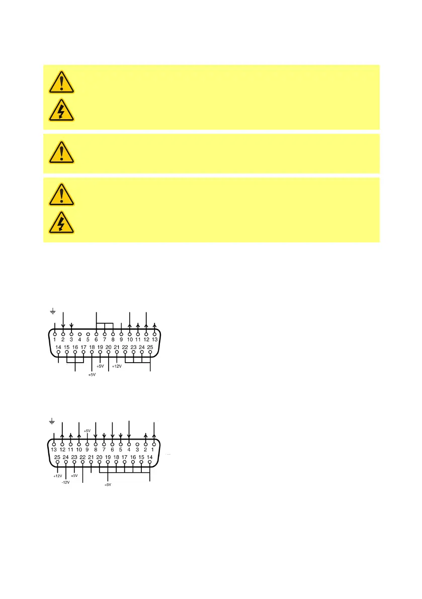
13.1 Upper D-connector
Recommended control cable: 7/0.2mm 24AWG screened. Cable screen should be earthed with a 360 deg
connection to a conductive back-shell. This will be connected to pump mains EARTH via the D connector
body. Mains Earth is also available on pin 1 Upper D and pin 13 Lower D.
- do not
use
Reserved
- do not
use
Signal
ground
VAUX
(+22.5V)
Commoning terminals,
used for voltage supply
13.2 Lower D-connector
earth
Tacho mA
output
TTL
output 1
TTL
output 2
Dose
Direction
enable
Direction
4-20mA
or 0-10V
Tacho
0-10V
Tacho
frequency
+10V
reference
Analogue 2
The 0V of this pump is DC isolated (floating) from the pump mains Earth. However, do not allow pump
0V to exceed 10V from the pump mains earth through connection with remote equipment, to avoid
overstressing internal 0V to Earth EMI capacitors.
13.3 Standard - 25 way D: Inputs and Outputs
22 m-730un-en-08.1