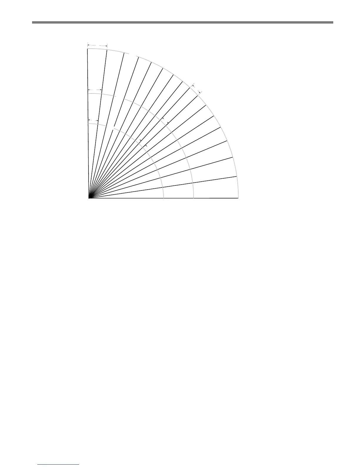
Figure E.1 – Matrix Beam Footprints
In an installation where the SmartSensor Matrix is installed in its preferred stop bar loca-
tion, angular resolution will likely not be a problem. is is because as the vehicles approach
the stop bar they will pass through the middle of the sensor’s view and be resolved. Also, as
the cars approach the stop bar they move into a more side-re orientation to the beams and
then can be resolved by their range dierences.
Using the extended range to monitor two approaches puts the sensor in a position where it
has to monitor lanes at its extreme edges. is is not a recommended application because
the beams are the widest at the edge of the sensor’s view, resulting in unfavorable angular
resolution.