CHAPTER 3 CONTACT CLOSURE COMMUNICATION 35
As shown in the table below, the outputs are mapped sequentially—that is, they can only
be mapped in numerically ordered groups of four (1–4, 5–8, etc.). If you set the switch to 3,
for 9–12, then sensor channel 9 would be mapped to output 1, sensor channel 10 would be
mapped to output 2, sensor channel 11 would be mapped to output 3, and sensor channel
12 would be mapped to output 4.
Switch Channels
0 Software mode
1 1–4
2 5–8
3 9–12
4 13–16
5 17–20
6 21–24
7 25–28
8 29–32
9 33–36
Table 3.1 – Click 104 Rotary Switch Channel Input Map Settings
Attaching and Programming the Click 112/114
Use the following steps to set up the contact closure rack cards for each sensor:
1 Make sure the DIP switches are set according to Figure 3.3 for a Click 114 and Figures
3.4 and 3.5 for Click 112 cards.
2 Power all the cards by plugging them into the detector rack.
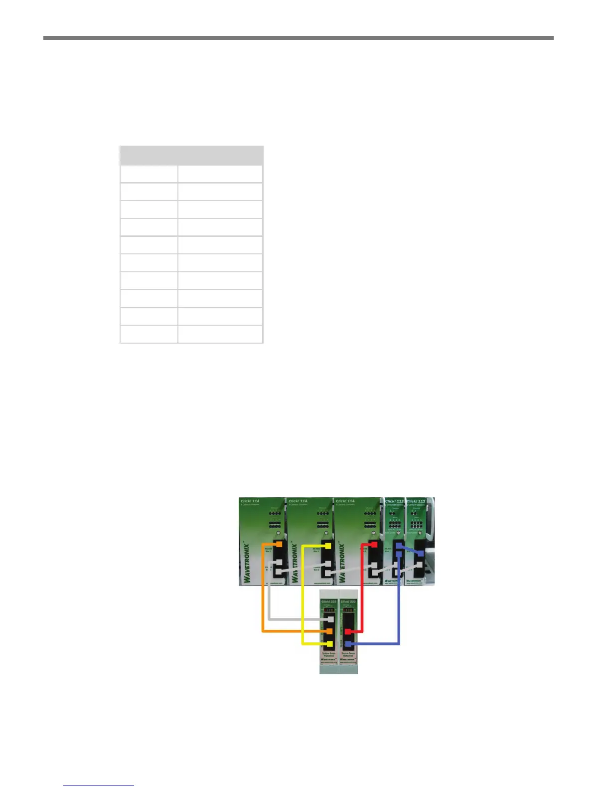
Figure 3.6 – Wiring the Click 112/114 Rack Cards
3 Connect a 6-. (1.8-m) patch cord from the Click 222 RS-485 A port to a bus 1 port on
the appropriate rack card (see Figure 3.6).