1 Introduction
WU017834 Rev. 05 July 2023 Wayne Fueling Systems | Dover Fueling Solutions 9
1 INTRODUCTION
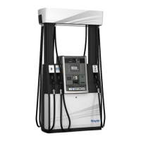
This manual covers information on the installation, operation and maintenance of the Wayne Helix
™
dis-
penser models with the metal head outlined in Dispensers Covered
, below. This manual also includes instal-
lation and footprint drawings that show locations of the product inlets and conduits. Computer function
settings that are necessary for Helix dispenser start-up and operation such as setting prices, blend ratios,
and fueling point IDs are also included. If additional information on function settings and statistics is
required, refer to the iGEM Computer Programming Manual (P/N WM048524).
1.1 DISPENSERS COVERED
This manual covers Helix 4000 (narrow) and 5000 (wide) model dispensers excluding Ultra-High Capacity
models, whose attributes can be determined by referring to the Model String Designation in Figure 1-1
. The
dispenser model number can be located on the serial number plate, receipts, or shipping documentation.
Helix models for ethanol blends up to E85 have the letter E on the model designation (e.g. H(W/LU)45-43ER)
and use the Xflo meter, product tubes, and outlet castings that have been specially evaluated for E85. Internal
fluid confining parts shall only be replaced with identical parts. External parts such as pipes, nipples, and fittings
that come into contact with the ethanol fuel must be ethanol-compatible and made only with Schedule 40 pipe
using UL-classified Saf-T-Lok Teflon pipe sealant. E85 dispensers may only use approved hanging hardware as
specifically indicated on the dispenser label. Replacement filters should be 10 microns.
Figure 1-1 Helix Model String Designation
STYLE
C = C-style
H = H-style
S = Small Style
DESIGN
W = Wide
N = Narrow
H = High Hose
L = Low Hose
ORIENTATION
ID = Island Dual Sided UI
IS = Island Single Sided UI
LM = Lane Mirrored
LU = Lane UnMirrored*
NO. GRADES IN
1 - 5
NO. GRADES OUT 1 - 8
If blender, count up +1 per each blending
possibility between 2 grades
NO.
HYDRAULIC
POSITIONS
0 - 5
NO. HOSES / NOZZLE POSITIONS PER SIDE
1 digit = Symmetric. Same number, solution, and
flows on both sides A & B.
2 digits = Asymmetric. Different number, solutions,
or flows on Sides A & B.
1st Digit = Side A
2nd Digit = Side B
BASIC TECHNICAL FEATURES
A = Additive
B = Biodiesel
C = CNG (Compressed Natural Gas)
D = DEF (Diesel Exhaust Fluid)
E = Ethanol
F = Fleet
G = Enhanced Capacity
H = Super-High Capacity
J = Ultra-High Capacity
K = E25 and B20 Compatible
L = LPG (Liquefied Petroleum Gas)
M = Media
P = Payment
R = Remote
S = Suction
T = Terminal
U = 4 Users
V = Vapor Recovery
W = Main (Back-to-Back)
X = Back
Y = SAT Master (Satellite)
Z = SAT Slave (Satellite)
a
b
c
d
e
f
gh
a b c d e f g h
X ( X / X ) X X - X X X
NOTE! Positions g and h contain
multiple digits.
Example:
H(W/LU)23-21PR
NOTE! The position prior to
and following the slash
'/' contains two (2) dig-
its as shown in this
example. 'LM' & 'LU'
specify 'Mirrored' &
'UnMirrored'.
 Loading...