15
INSTRUCTION MANUAL
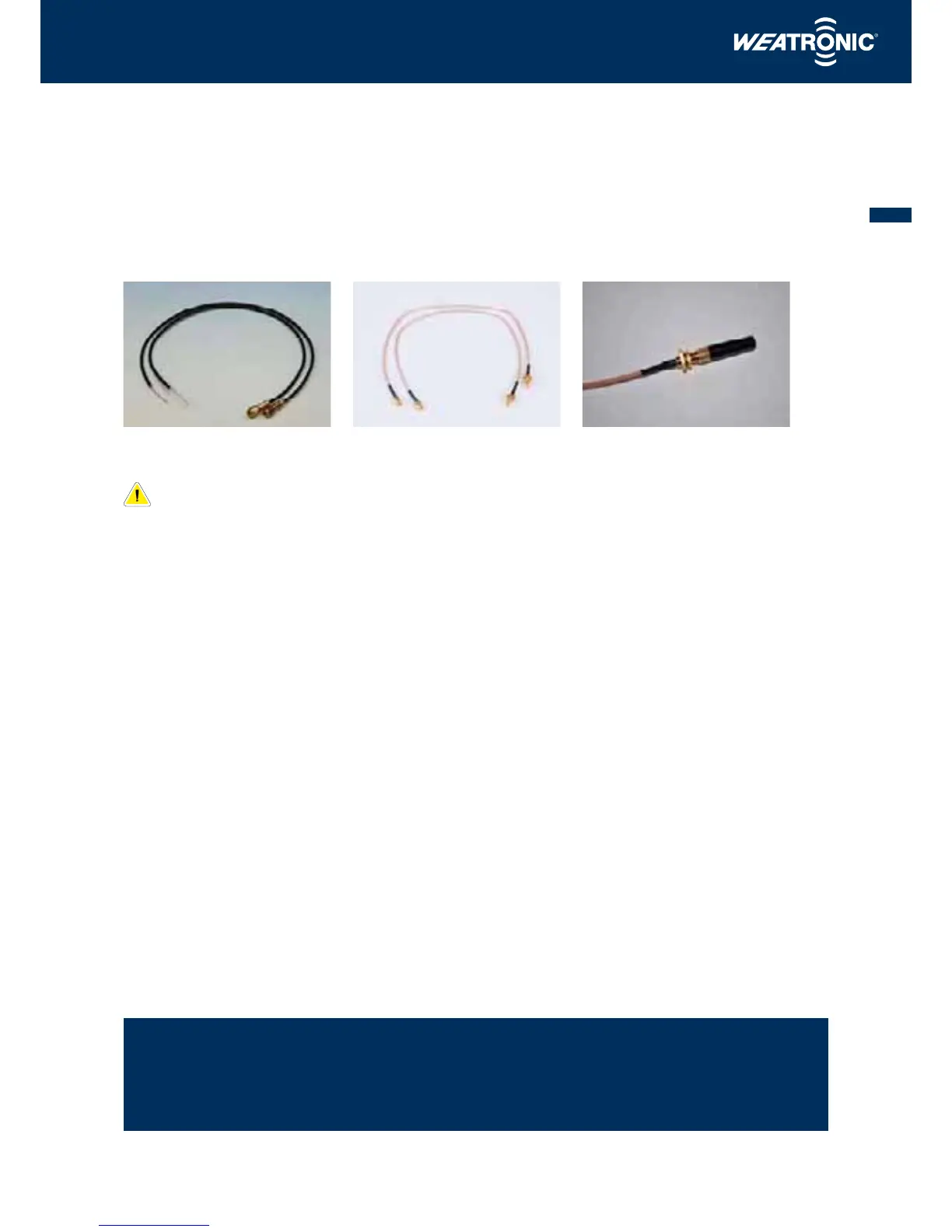
6.4 Routing the Dual 2.4 Dual FHSS 12-22 R series receiver antenna
The receiver is fitted with 2 shielded 200 mm long antennas which are equipped with SMA type screw sockets. The gold coloured locking nuts are
10 mm and should be gently hand tightened using a suitable short spanner. If the model is susceptible to vibration, a drop of ‘Pattex’ glue may be
applied to the threads to act as low tensile thread lock. In effect, only the last un-shielded 29 mms of the antenna receive the signal and they should
be located as far apart as possible at an angle of 90 degrees to each other. The antennas must lay straight and we recommend mounting them into
plastic tubes (NOT carbon fibre!) for protection.
Original antennas with SMA type connectors Coax cable extensions for external External stump areal for better reception
mounting with SMA type connectors
For fuselages which are constructed from Carbon fibre or those which have a high level of carbon fibre reinforcement we
recommend using extensions to mount the antennas outside of the fuselages (these are available in varying lengths).
Carbon fibre is a very good insulator against radio waves and mounting the antenna internally would greatly reduce the
range of the system. This warning also applies to models with metal or metallic coverings which includes metallic paint.
6.5 Safety notes
6.5.1 Checking the cables and soldered joints
We strongly recommend that you inspect all cables and soldered joints regularly for damage and that any damage is repaired immediately. Cables
and soldered joints are particularly susceptible to damage where vibration is present which is often the case with models. All soldered joints should
be re-enforced with heat shrink tube of the correct diameter.
6.5.2 Electronic ‘noise’ suppression – Electric motors
Convention brushed electric motors must have a suitable condenser fitted to suppress any electrical ‘noise’ that they may generate. Such electric
‘noise’ is created by the brush to collector contact and may cause severe interference to the receiver if it is not correctly suppressed. In particular,
the fuel pump fitted to a model jet’s turbine may create a considerable amount of electrical ‘noise’ and as such you should follow the manufactur-
ers recommendations closely when fitting the pump.
6.5.3 Electronic ‘noise’ suppression – Electronic ignition systems
Electronic and magnet driven ignition systems also produce high levels of electronic ‘noise’ which can cause interference or drastically reduce the
system’s range. Always use a separate battery supply for the ignition to enable you to place the pack as near as possible to the ignition unit and
keep the leads as short as possible. Spark plugs, plug caps and HT/LT cables must be screened and the receiver system including all servos and cables
should be kept as far as possible away from the ignition system.
6.6 Laying the cables for use on jets
The ECU must not be positioned near to the receiver (minimum distance 10 cms). All cabling for the ECU and its components (battery pack, pump,
data BUS, turbine cables etc.) must be kept away from the receiver system cables (receiver battery, servo, switch etc.).
www.weatronic.com