37
INSTRUCTION MANUAL
11.3.4.6.1 Channel Failsafe
You can decide whether you want the servos to hold the positi-
on where the last known good signal was received (‘Hold’), or
to move to a pre-determined point, for example, tick over for the
engine (‘Failsafe’). To choose one of these options the servo map-
ping window has to be opened. Within this window on the right
hand side is a field labelled Failsafe type, in this column are boxes
for each channel. Each box should be set to ‘F’ for ‘Failsafe’ or ‘H’
for ‘Hold’ by clicking it with the left mouse button. If you have
selected ‘F’ for any function click onto that function with the right
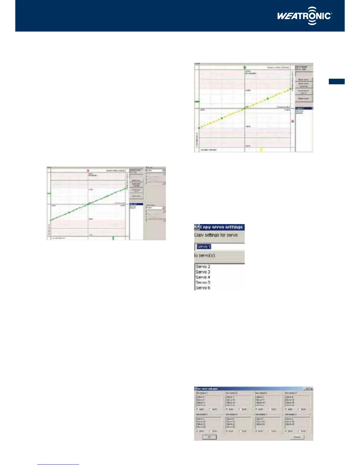
mouse to open the Configure servo window. A green dot is visible
in the upper bar and by clicking onto this dot with the left mouse
button and moving it to the left or right the Failsafe position can
be set for that channel and the dot will turn to red to indicate that
it has been set. The position of the dot will be displayed in the box
to the right of the field both as a percentage and in steps (max.
+/- 2048).
The red dot in the upper field shows a Failsafe position of – 13%.
If ‘H’ for hold has been selected, the green dot will not appear as
the last known good signal position will automatically be held.
11.3.4.6.2 Servo Failsafe
If a group of servos or devices have been allocated to one channel
(transmitter function) each individual servo can be independently
programmed. In the example below, servos 7, 8 and 9 have been
linked to channel (transmitter function) 7. By left mouse clicking
the field labelled ‘Servo failsafe’ a tick will appear in the box and
a red dot can be seen in the right hand column (labelled Failsafe
position servo). The desired Failsafe position can now be set by left
mouse clicking the red button and dragging it up or down. This
procedure can be applied to all of the remaining servos
Servo 8 has been set to a Failsafe position of – 65% (the position
of the red dot).
11.3.4.7 Copying servo settings
Once you have found the correct setting for one servo, these values
can be copied to another servo by using the ‘Copy servo settings’
function. To access this function click on the button located at the
bottom of the ‘Servo mapping’ window.
In the upper field you can select the servo setting which you want
to copy and in the lower field is a list of the servos which the
settings can be copied to.
Once you have selected the ‘from’ and the ‘to’ servos in the rele-
vant boxes, click ‘OK’ to copy the settings.
11.3.4.8 Setting the servo voltage
The 2.4 Dual FHSS 12 – 22 R series of receivers are fitted with 8
separate regulated circuits to power the servos and the voltage
for each circuit can be set to 4.8 or 6.0 Volts. The voltage for each
circuit can be set by accessing the ‘Servo voltages’ function. To do
this click on the button which is located on the bottom right of the
‘Servo mapping’ window: