36
“Invert curve (channel)“:
By clicking on this button the transmitter function will be reversed,
i.e. left stick will produce a right stick reaction from the receiver
and the function will be reversed.
“Invert curve (servo)”:
By clicking this button the direction of rotation of the servo will be
reversed, and each servo can have its direction changed indepen-
dently. This function is useful when more than one servo is grouped
together to ensure that the linkages can be fitted to the correct
side of the servo.
“Reset curve“:
This button will return the curve to the default settings.
The limit lines “Minimum” and “Maximum” are fully explained in
the sections “Mixer Special” and “Giro Special”.
The default settings for the servo curves allocates them 5 points
which are indicated by the dots
Servo curve adjustment points
The green dots are the points at which the servo curve can be
altered by simply clicking onto them (left mouse button) which
will cause them to turn red (active) and they can then be moved
by dragging them up or down. You can also use the arrow keys to
move them ¥£¢¤. In addition to the 5 fixed points, each servo
curve for the Master servo of a group or a single servo can have up
to 31 adjustment points added to them.
To add an adjustment point, use the right mouse button to click
onto one of the smaller dark dots which will ‘active’ it, it will then
become an adjustment point which can be tailored as explained in
the paragraph above. If you want to reverse the selection, use the
right mouse button once again to click onto the Point and it will
revert to a small dark dot.
Each ‘active ‘point can now be moved as required which will allow
you to tailor the curve to create, for example, an exponential func-
tion to ‘fine tune’ the control response of your model as illustrated
below.
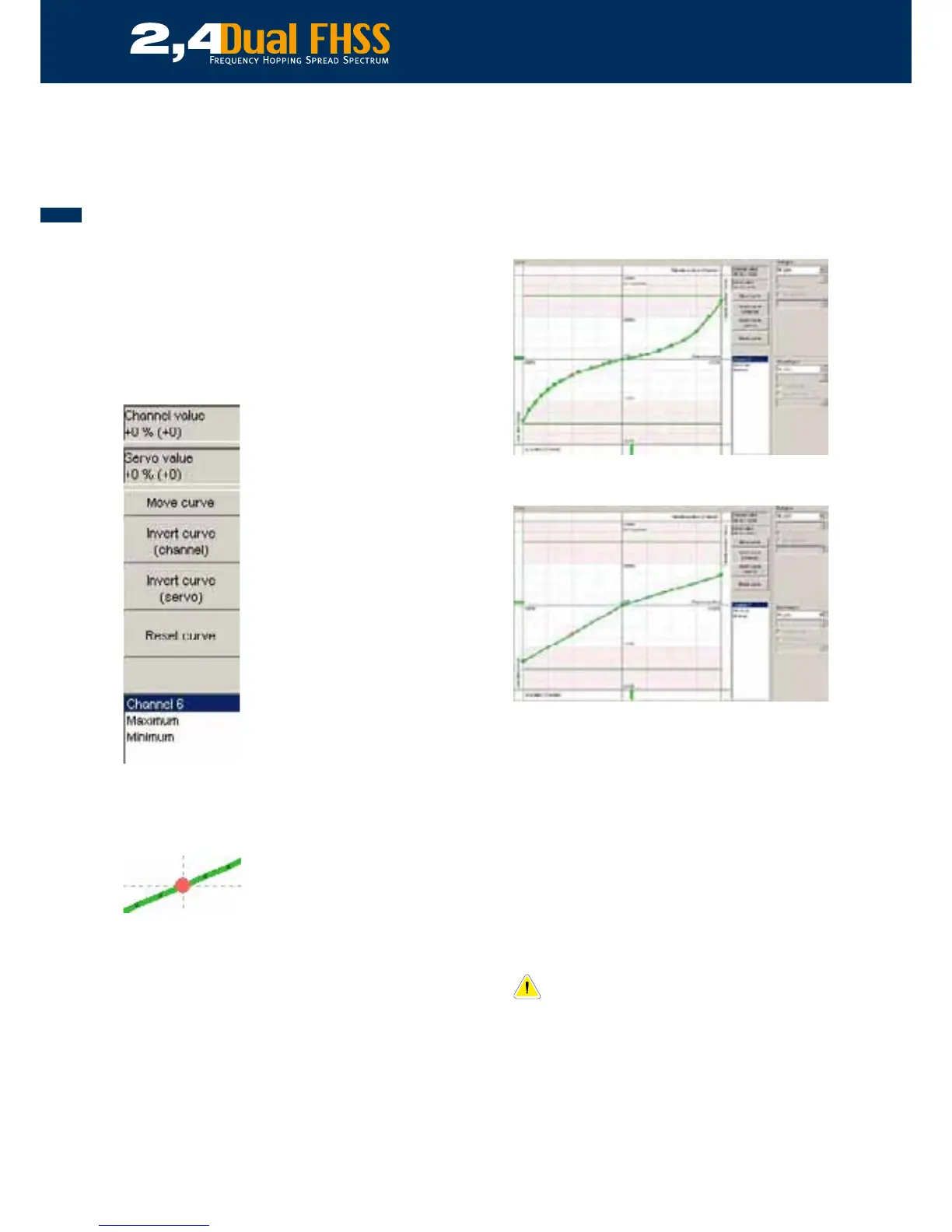
Example of a servo curve which will create an exponential move-
ment of the servo
A servo curve which has been tailored to create differential mo-
ment which be useful if, for example, you want your ailerons to
have move movement up than down to prevent adverse drag.
11.3.4.6 Failsafe settings
Your weatronic R/C system will ignore any Failsafe signals trans-
mitted by your transmitter, this is because we have incorporated
our own user-friendly multi-function Failsafe system. Firstly, please
refer to Para. 11.3.2 to learn how to set the Failsafe time out value
which can be set between 100 milliseconds and 1 second.
In the unlikely event that the receiver looses the transmitter signal,
the servos will move to a pre-determined ‘Failsafe’ position or, if no
Failsafe position has been set, they will ‘Hold’ where they are.
If no Failsafe position has been set, the system will
default to the factory setting. The factory setting is
the neutral or middle point for all servos and func-
tions
Weatronic differentiates between ‘Channel Failsafe’ and ‘Servo
Failsafe’. The Channel Failsafe function will apply to all servos
linked to that function and Servo Failsafe allows you to program
individual servos allocated to a channel singularly.