EasyManua.ls Logo

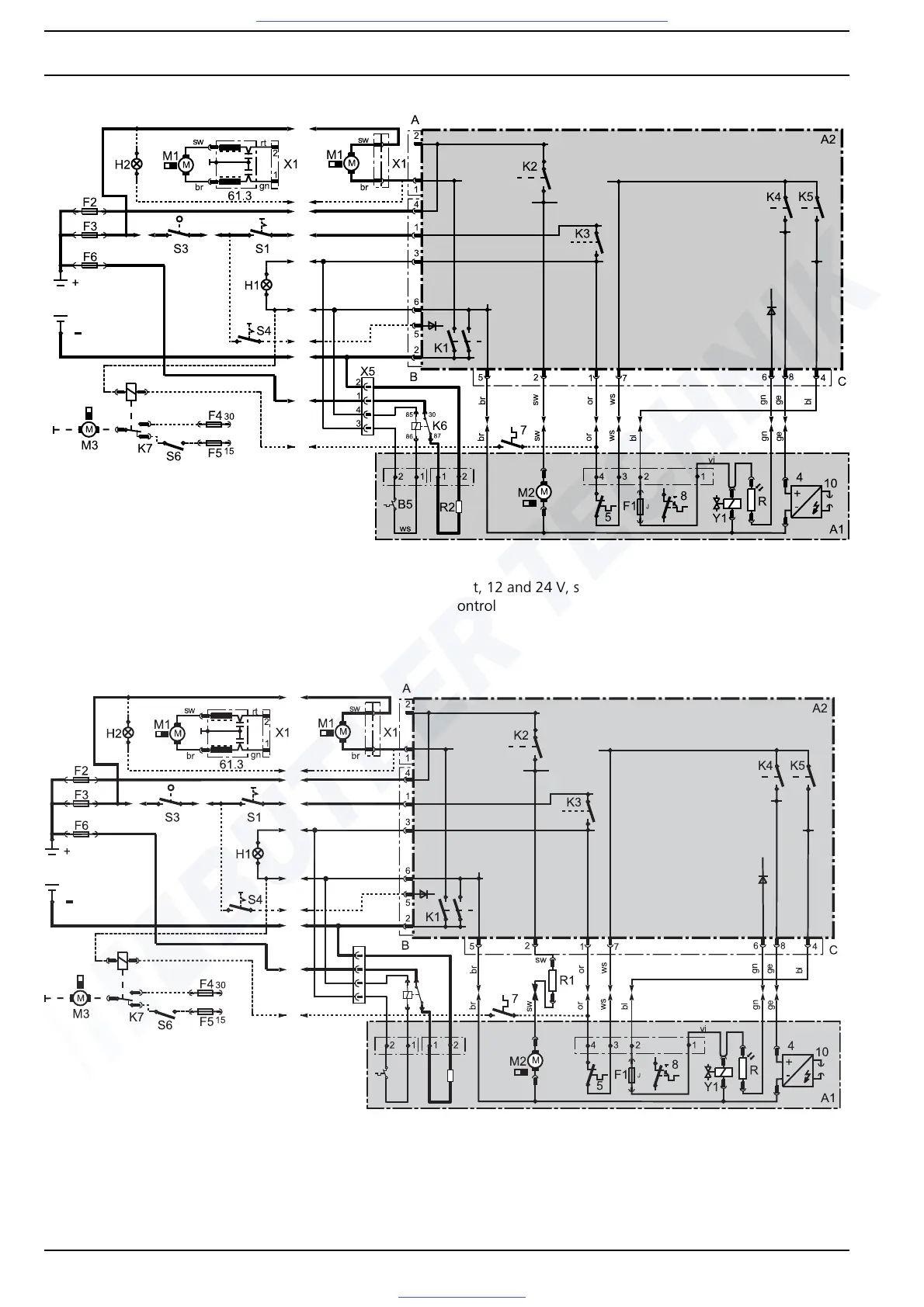
Webasto DBW 2016 - Fig. 703 System Wiring Diagram DBW 2010 with 1553 Control Unit, 12 and 24 V, Switch, Nozzle Holder; Fig. 704 System Wiring Diagram DBW 2016 with 1553 Control Unit, 24 V, Switch, Nozzle Holder

Webasto DBW 2016
78 pages
Print Icon
To Next Page IconTo Next Page
To Previous Page IconTo Previous Page
Loading...
7 Circuit Diagrams DBW 2010 / 2016
704
Fig. 703 System wiring diagram DBW 2010 with 1553 control unit, 12 and 24 V, switch, nozzle holder pre-heating unit and
altitude control
Fig. 704 System wiring diagram DBW 2016 with 1553 control unit, 24 V, switch, nozzle holder pre-heating unit and altitude
control

B5
R2
ws
X5
1
2
3
4
87
3085
86
K6
Visit www.butlertechnik.com for more technical information and downloads.
www.butlertechnik.com

Table of Contents