www.weg.net
22 l Installation, Operation and Maintenance Manual – Synchronous Motors – S Line – Brushless – Horizontal 11866576
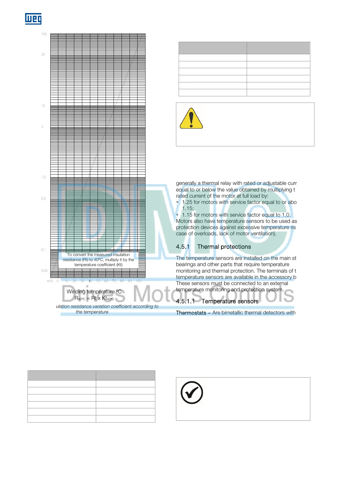
Figure 4.3: Insulation resistance variation coefficient according to
the temperature
4.4.8 Insulation assessment
Table 4.2 and Table 4.3 present guiding limits of insulation
resistance and polarization index for the assessment of
the motor insulation conditions.
Table 4.2: Insulation resistance referential limits on electrical
machines
Insulation resistance value Insulation assessment
2 M or lower
Unacceptable
< 50 M
Dangerous
50...100 M
Fair
100...500 M
Good
500...1000 M
Very Good
> 1000 M
Excellent
Table 4.3: Polarization index (ratio between 10 minutes and 1
minute)
Polarization index Insulation assessment
1 or lower Unacceptable
< 1.5 Dangerous
1.5 to 2.0 Fair
2.0 to 3.0 Good
3.0 to 4.0 Very Good
> 4.0 Excellent
TTENTION
If the measured insulation resistance, referred
to 40 ºC, is below 100 M or the polarization
index is below 2, before putting the motor into
operation, consult WEG.
4.5 PROTECTIONS
Motors used in continuous duty must be protected
against overloads by means of a motor integral device,
generally a thermal relay with rated or adjustable current
equal to or below the value obtained by multiplying the
rated current of the motor at full load by:
1.25 for motors with service factor equal to or above
1.15;
1.15 for motors with service factor equal to 1.0.
Motors also have temperature sensors to be used as
protection devices against excessive temperature rise (in
case of overloads, lack of motor ventilation).
4.5.1 Thermal protections
The temperature sensors are installed on the main stator,
bearings and other parts that require temperature
monitoring and thermal protection. The terminals of the
temperature sensors are available in the accessory box.
These sensors must be connected to an external
temperature monitoring and protection system.
4.5.1.1 Temperature sensors
Thermostats – Are bimetallic thermal detectors with
normally closed silver contacts. They open at a certain
temperature. The thermostats are connected in series or
independently according to the connection diagram.
Thermistors (PTC or NTC) - Are thermal detectors
composed of semiconductors that vary their resistance
sharply when they reach a certain temperature.
Thermistors are connected in series or independently
according to the connection diagram.
NOTE
Thermostats and thermistors must be
connected to a control unit in order to
interrupt the motor operation or activate a
signaling device.
RTDs (Pt100) - Are calibrated resistance elements. Their
operation is based on the principle that the electrical
resistance of a metallic conductor varies linearly with the
temperature. The detector terminals must be connected
to a control panel which includes a temperature meter.
Winding temperature ºC
R
40ºC
= Rt x Kt
40ºC
o convert the measured insulation
resistance (Rt) to 40ºC, multiply it by the
temperature coefficient (Kt)
Coefficient of insulation resistance variation Kt
40ºC
 Loading...


