www.weg.net
30 l Installation, Operation and Maintenance Manual – Synchronous Motors – S Line – Brushless – Horizontal 11866576
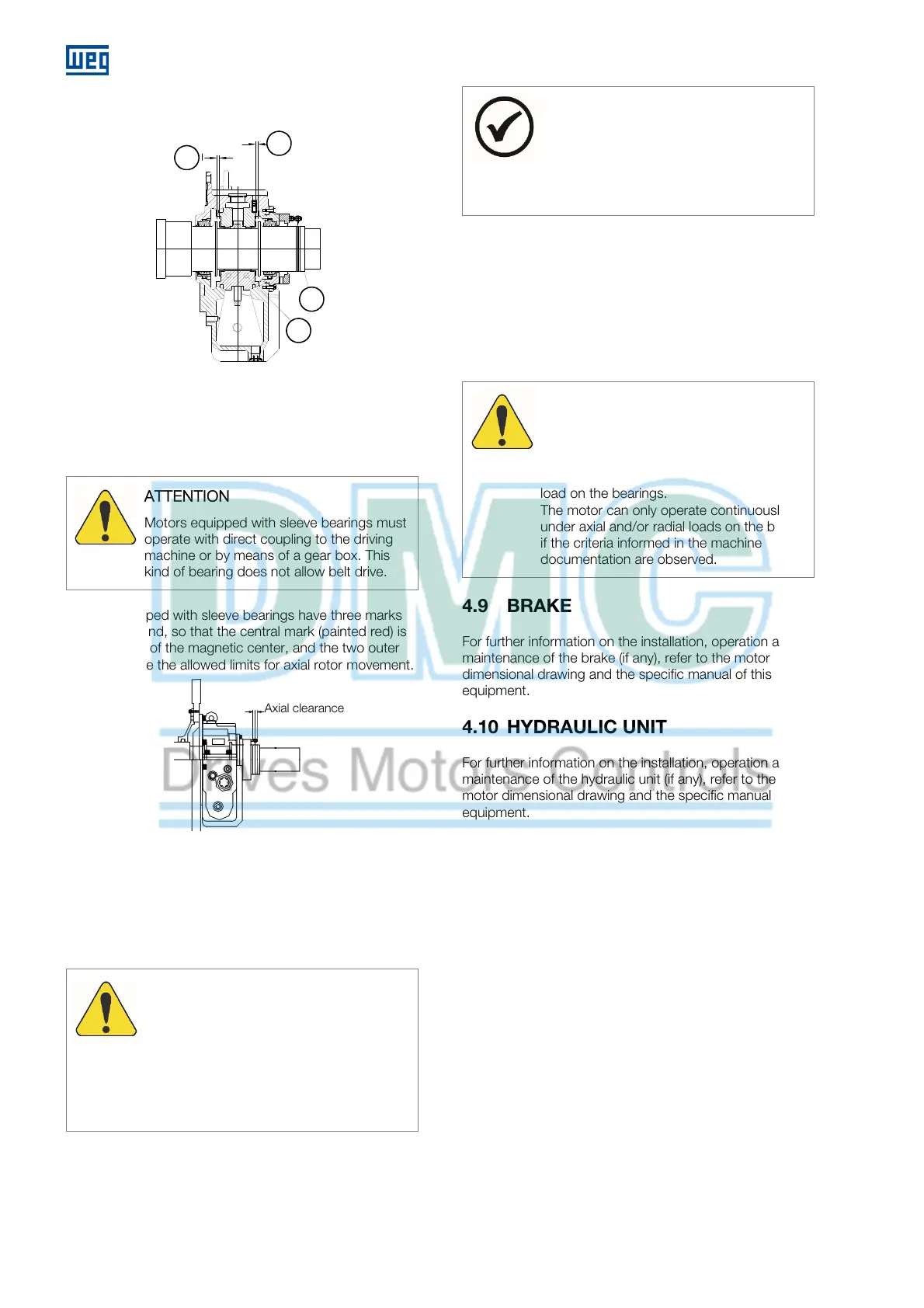
4.8.10.3 Coupling of motors equipped with
sleeve bearings
Figure 4.10: Sleeve bearing
Figure 4.10 legend:
1. Axial clearance
2. Shaft
3. Bearing shell
TTENTION
Motors equipped with sleeve bearings must
operate with direct coupling to the driving
machine or by means of a gear box. This
kind of bearing does not allow belt drive.
Motors equipped with sleeve bearings have three marks
on the shaft end, so that the central mark (painted red) is
the indication of the magnetic center, and the two outer
marks indicate the allowed limits for axial rotor movement.
Figure 4.11: Magnetic center mark
For the motor coupling, the following factors must be
taken into account:
Bearing axial clearance;
Axial displacement of the driving machine (if any);
Maximum axial clearance allowed by the coupling.
TTENTION
Move the shaft completely forwards and
then perform the correct measurement of
the axial clearance;
Align the shaft ends carefully and,
whenever possible, use flexible coupling,
leaving a minimum axial clearance of 3 to
4 mm between the couplings.
NOTE
If it is not possible to move the shaft, then
the shaft position, the shaft forward
displacement (according to the marks on the
shaft), and the axial clearance recommended
for the coupling must be considered.
Before putting it into operation, it is necessary to check
whether the motor shaft allows free axial movement
within the aforementioned clearance conditions;
In operation, the arrow must be positioned on the
central mark (red), which indicates that the rotor is in its
magnetic center;
During the start, or even in operation, the motor may
move freely between the two outer limit marks.
TTENTION
The sleeve bearings used on this motor were
not designed to withstand constant axial
loads; therefore, under no circumstances can
the motor continuously operate under axial
load on the bearings.
The motor can only operate continuously
under axial and/or radial loads on the bearing
if the criteria informed in the machine
documentation are observed.
4.9 BRAKE
For further information on the installation, operation and
maintenance of the brake (if any), refer to the motor
dimensional drawing and the specific manual of this
equipment.
4.10 HYDRAULIC UNIT
For further information on the installation, operation and
maintenance of the hydraulic unit (if any), refer to the
motor dimensional drawing and the specific manual of this
equipment.
Folga axial
1
1
2
3
xial clearance
 Loading...


