www.weg.net
11866576 Installation, Operation and Maintenance Manual – Synchronous Motors – S Line – Brushless – Horizontal l 41
NOTE
When testing the diodes, observe the polarity
of the test terminals regarding the diode
polarity.
1. Loosen the flexible cables of the 6 diodes;
2. With an ohmmeter, measure the resistance of each
diode in both directions.
The diode is considered good when it presents low
resistance (up to ± 100Ω) in its direct direction and high
resistance (approximately 1 MΩ) in the reverse direction.
Defective diodes will have a resistance of 0 Ω or greater
than 1 MΩ in both directions. In most cases, the test
method which uses an ohmmeter is sufficient to identify
faults in the diodes. However, in some extreme cases it
may be necessary to apply the blocking rated voltage
and/or current circulation in order to detect fault in the
diodes. Because of all the effort required to perform these
tests, in case of doubt, it is recommended replace the
diodes.
7.9.3.1
Diode Replacement
To replace any of the diodes, proceed according to the
following directions:
1. Replace the damaged diodes by new diodes identical
to the original ones, observing the position of each
anode diode and each cathode diode;
2. The diodes are already supplied with insulated braided
cable and connection terminal;
3. Clean the heatsink disk completely around the diode-
mounting hole.
4. Check if the diode thread is clean and free of burs;
5. Apply thermal compound on the contacts;
6. Install the diode in its correct position using a torque
wrench, observing the torques recommended in Table
7.1
.
Table 7.1: Diode tightening torque
Thread of the
diode base (mm)
Torque wrench
head (mm)
Tightening
torque
(Nm)
M12 24 10
M16 32 30
M24 41 60
TTENTION
It is of fundamental importance that the
torque be respected in order to prevent
damages to the diodes during the assembly.
7. After fastening the diodes, connect their ropes.
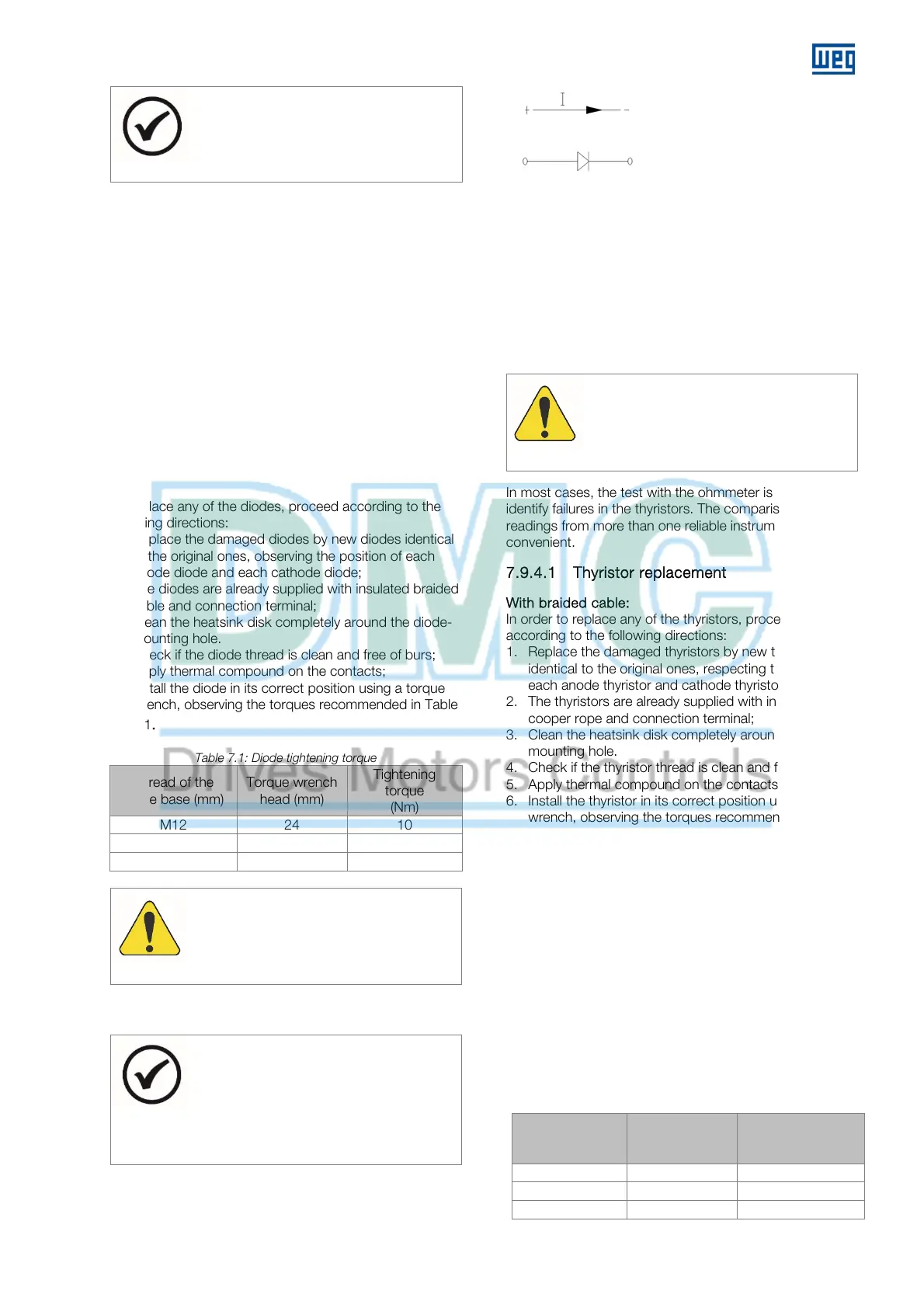
NOTE
The polarity of the diode is indicated by an
arrow on its housing. When replacing the
diodes, make sure they are installed in each
part of the heatsink disk with the correct
polarity.
The current conduction must
occur only in the anode-
cathode direction, i.e. in the
condition of direct polarization.
7.9.4
Thyristor test
Disconnect the thyristors to be tested from the circuit by
disconnecting the rope, the gate terminals and the
cathode.
The thyristor in good conditions presents high resistance
in both directions. When defective, normally the reading is
close to zero in both directions.
The thyristor gate circuit must present low resistance (25 –
100 ohms) in both directions.
TTENTION
pplying more than 10 V to the thyristor gate
may damage the triggering circuit and result in
damages to the motor.
In most cases, the test with the ohmmeter is sufficient to
identify failures in the thyristors. The comparison of
readings from more than one reliable instrument is
convenient.
7.9.4.1
Thyristor replacement
With braided cable:
In order to replace any of the thyristors, proceed
according to the following directions:
1. Replace the damaged thyristors by new thyristors
identical to the original ones, respecting the position of
each anode thyristor and cathode thyristor;
2. The thyristors are already supplied with insulated
cooper rope and connection terminal;
3. Clean the heatsink disk completely around the thyristor
mounting hole.
4. Check if the thyristor thread is clean and free of burs;
5. Apply thermal compound on the contacts;
6. Install the thyristor in its correct position using a torque
wrench, observing the torques recommended in Table
7.2
7. After fastening the thyristors, connect their ropes.
Disk thyristor:
In order to replace any of the thyristors, proceed
according to the following directions:
1. Replace the damaged thyristors by new thyristors
identical to the original ones, respecting the position of
each thyristor and the correct anode and cathode
positions;
2. Clean the heatsink completely on the contact areas;
3. Apply thermal compound on the contacts;
4. The thyristor must be mounted on the support and the
wires of the gate terminal must be welded and
insulated with heat shrink tubing;
5. Apply a tightening torque of 10Nm.
Table 7.2: Thyristor tightening torque
Thread of the
thyristor base
(mm)
Torque wrench
head (mm)
Tightening torque
(Nm)
M12 24 10
M16 32 30
M24 41 60
 Loading...


