www.weg.net
48 l Installation, Operation and Maintenance Manual – Synchronous Motors – S Line – Brushless – Horizontal 11866576
8 MOTOR DISASSEMBLY AND ASSEMBLY
TTENTION
ll the repair, disassembly and assembly services must be performed only by properly qualified and trained
professionals; otherwise, equipment damage and personal injury may occur. If any further explanations are
necessary, consult WEG.
The disassembly and assembly sequence depend on the motor model.
lways use proper tools and devices. Any damaged part (cracks, dents on machined parts, faulty threads)
must be replaced, avoiding restorations.
8.1 DISASSEMBLY
The following precautions must be taken when
disassembling the electric motor:
1. Always use proper tools and devices to disassemble
the motor;
2. Before disassembling the motor, disconnect the
cooling water and lubrication pipes (if any);
3. Disconnect the motor electrical connections and
those of the accessories;
4. Remove the heat exchanger and the noise
suppressor (if any);
5. Remove the bearing temperature sensors and the
grounding brush;
6. In order to prevent damages to the rotor and coil
heads, support the shaft on both drive and non-drive
ends;
7. In order to disassemble the bearings, follow the
procedures described in this manual;
8. The removal of the rotor from the motor must be
done with a suitable device and with extreme care so
that the rotor does not drag on the stator laminated
core or coil heads, thus preventing damages.
8.2 ASSEMBLY
To assemble the motor, follow the disassembly procedure
in the reverse order.
NOTE
When the motor is supplied disassembled,
an assembly manual is provided with it,
describing the procedures for assembly on
site.
lways use proper tools and devices to
assemble the motor;
ny damaged part (cracks, dents on
machined parts, faulty threads) must be
replaced, always avoiding restorations.
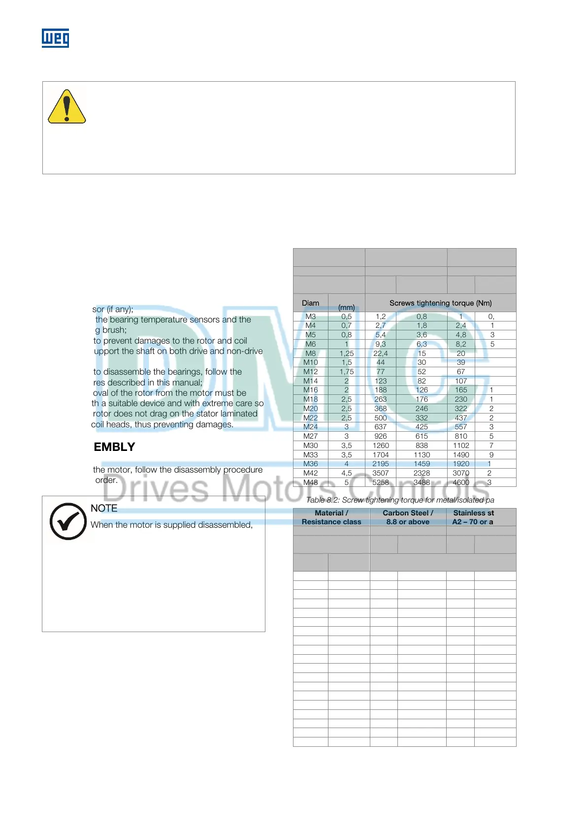
8.3 TIGHTENING TORQUE
Table 8.1 and Table 8.2 shows the tightening torques of
the screws recommended for assembling the motor.
Table 8.1: Screw tightening torque for metal/metal parts
Material /
Resistance class
Carbon Steel /
8.8 or above
Stainless steel /
A2 – 70 or above
% Yield Strength 60% 70%
Lubricant Dry
Molycote
1000
Dry
Molycote
1000
Diam
Pitch
(mm)
Screws tightening torque (Nm)
M3 0,5 1,2 0,8 1 0,69
M4 0,7 2,7 1,8 2,4 1,6
M5 0,8 5,4 3,6 4,8 3,2
M6 1 9,3 6,3 8,2 5,5
M8 1,25 22,4 15 20 13
M10 1,5 44 30 39 26
M12 1,75 77 52 67 45
M14 2 123 82 107 72
M16 2 188 126 165 110
M18 2,5 263 176 230 154
M20 2,5 368 246 322 215
M22 2,5 500 332 437 290
M24 3 637 425 557 372
M27 3 926 615 810 538
M30 3,5 1260 838 1102 734
M33 3,5 1704 1130 1490 990
M36 4 2195 1459 1920 1277
M42 4,5 3507 2328 3070 2037
M48 5 5258 3488 4600 3052
Table 8.2: Screw tightening torque for metal/isolated parts
Material /
Resistance class
Carbon Steel /
8.8 or above
Stainless steel /
A2 – 70 or above
% Yield Strength 33% 33%
Lubricant Dry
Molycote
1000
Dry
Molycote
1000
Diam
Pitch
(mm)
Screws tightening torque (Nm)
M3 0,5 0,6 0,5 0,48 0,32
M4 0,7 1,5 1 1,1 0,76
M5 0,8 3 2 2,2 1,5
M6 1 5,2 3,4 3,8 2,6
M8 1,25 12,3 8,3 9,2 6,2
M10 1,5 24 16 18,2 12,2
M12 1,75 42 28 32 21
M14 2 68 45 51 34
M16 2 104 69 78 52
M18 2,5 145 98 108 72
M20 2,5 202 135 152 101
M22 2,5 274 183 206 137
M24 3 350 233 263 175
M27 3 510 338 382 254
M30 3,5 693 461 520 346
M33 3,5 937 622 703 466
M36 4 1207 802 905 602
M42 4,5 1929 1280 1447 960
M48 5 2892 1918 2170 1440
 Loading...


