www.weg.net
28 l Installation, Operation and Maintenance Manual – Synchronous Motors – S Line – Brushless – Horizontal 11866576
Half of the difference between the dial gauge
measurements at the 90º and 270º points represents the
horizontal coaxial error.
These measurements indicate when it is necessary to lift
or lower the motor, or move it to the right or to the left on
the drive end in order to eliminate the coaxial error.
Half of the maximum difference among the dial gauge
measurements in a complete rotation represents the
maximum eccentricity found.
The misalignment in a complete shaft rotation, with rigid or
semiflexible coupling, cannot exceed 0.03 mm.
When flexible couplings are used, greater values than
those indicated above are acceptable, provided that they
do not exceed the value allowed by the coupling
manufacturer.
It is recommended to keep a safety margin for these
values.
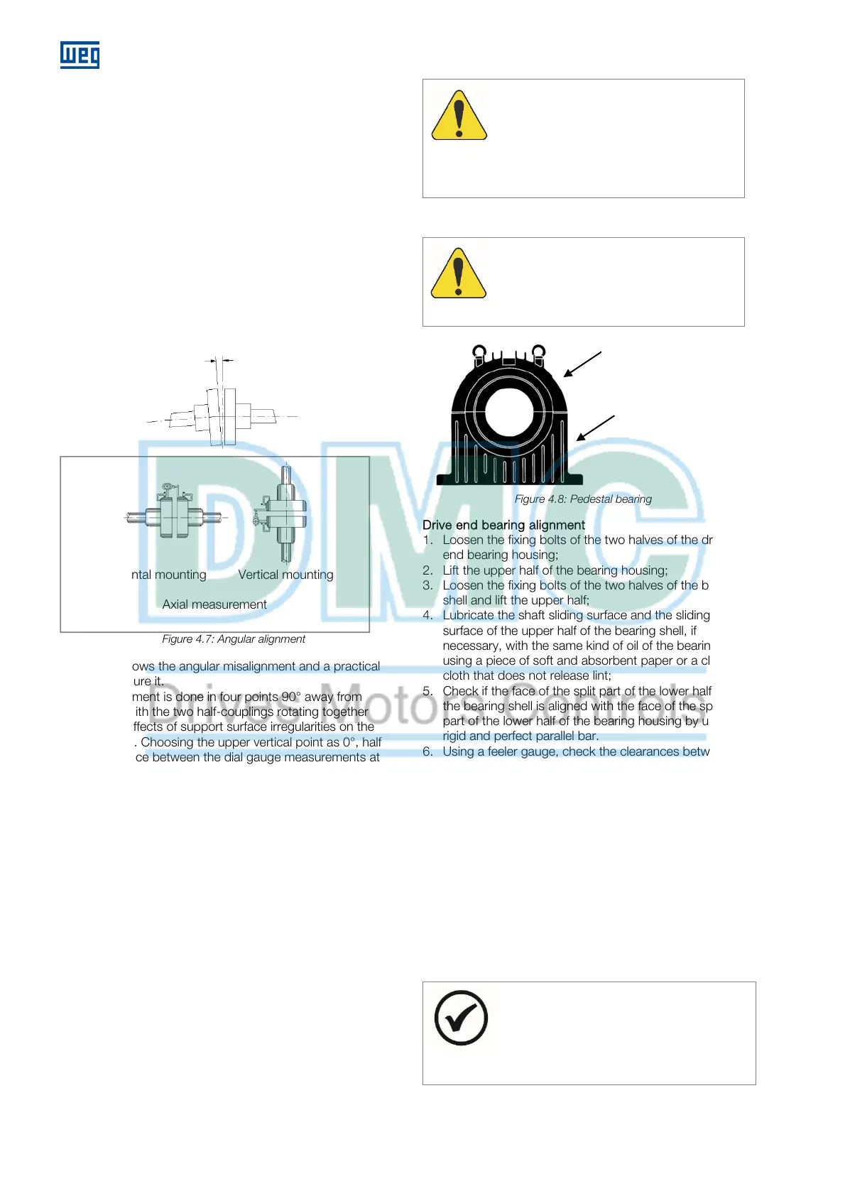
Figure 4.7: Angular alignment
Figure 4.7 shows the angular misalignment and a practical
form to measure it.
The measurement is done in four points 90° away from
each other, with the two half-couplings rotating together
to eliminate effects of support surface irregularities on the
dial gauge tip. Choosing the upper vertical point as 0°, half
of the difference between the dial gauge measurements at
the 0° and 180° points represents the vertical
misalignment. In case of deviation, it must be corrected by
adding or removing alignment shims.
Half the difference between the dial gauge measurements
at the 90° and 270° points represents the horizontal
misalignment, which must be corrected by displacing the
motor in the lateral/angular direction.
Half of the maximum difference among the dial gauge
measurements in a complete rotation represents the
maximum angular misalignment found.
The misalignment in a complete shaft rotation, with rigid or
semiflexible coupling, must not exceed 0.03 mm. When
flexible couplings are used, greater values than those
indicated above are acceptable, provided that they do not
exceed the value allowed by the coupling manufacturer.
It is recommended to keep a safety margin for these
values.
In the alignment/leveling, the influence of temperature on
the motor and coupled machine must be taken into
account. Different expansions of the parts may change the
alignment/leveling conditions during operation.
TTENTION
fter aligning the set and having assured a
perfect alignment
(both hot and cold)
, the
motor must be doweled to the anchor plate
or to the base, according to the information
in the motor dimensional drawing.
4.8.9
Inspection of pedestal bearings
TTENTION
Pedestal bearings must be inspected and, if
necessary, realigned according to the
instructions below:
Figure 4.8: Pedestal bearing
Drive end bearing alignment
1. Loosen the fixing bolts of the two halves of the drive
end bearing housing;
2. Lift the upper half of the bearing housing;
3. Loosen the fixing bolts of the two halves of the bearing
shell and lift the upper half;
4. Lubricate the shaft sliding surface and the sliding
surface of the upper half of the bearing shell, if
necessary, with the same kind of oil of the bearing
using a piece of soft and absorbent paper or a clean
cloth that does not release lint;
5. Check if the face of the split part of the lower half of
the bearing shell is aligned with the face of the split
part of the lower half of the bearing housing by using a
rigid and perfect parallel bar.
6. Using a feeler gauge, check the clearances between
the lower half of the bearing shell and the shaft in four
points (right, left, front and back sides of the bearing
shell);
7. In case the measured clearances are different, or the
faces of the split parts of the bearing shell are
misaligned with the faces of the split part of the
bearing housing, the bearing shell must be aligned
with the shaft, as follows:
8. Loosen the fixing bolts of the two halves of the non-
drive end bearing housing before lifting the shaft;
9. Lift the drive end of the motor shaft just enough for the
rotor weight not to rest on the bearing shell so that it
can be adjusted in the spherical seat of the lower half
of the bearing housing;
NOTE
Between the shaft and the lifting device, use a
material softer than the shaft material, in order
to prevent damages (copper or bronze, for
instance).
Bearing upper hal
Bearing lower half
Horizontal mounting Vertical mounting
Axial measurement
Angular misalignment
 Loading...


